


During the collection and editing of spatial data, some errors inevitably occur. For example, the same node or line being digitized twice, adjacent polygon features developing gaps or intersections during collection, or unclosed features. These errors often generate topology errors such as pseudo nodes, redundant vertices, dangling arcs, duplicate lines, etc., causing discrepancies between the topological relationships in collected spatial data and real-world features. This affects subsequent data processing, analysis workflows, and compromises data quality and usability. Moreover, these topology errors are typically numerous, concealed, and difficult to identify manually. Therefore, topology processing is required to rectify these redundancies and errors.
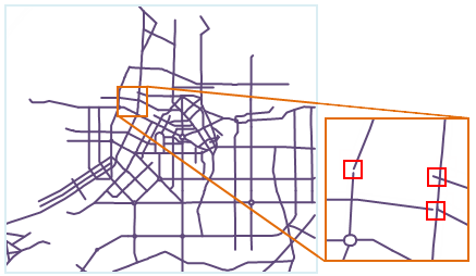 |
| Figure: Schematic Diagram of Topology Errors |
Topology processing refers to the procedure of repairing or preventing topology errors, comprising inspection and rectification steps. It includes seven rules: Remove Pseudo Nodes, Remove Redundant Vertices, Remove Duplicate Lines, Remove Overshoots, Extend Undershoots, Merge Adjacent Ends, and Intersect Arcs. Appropriate tolerance settings for different rules during processing are crucial for optimal results.
This product primarily performs topology processing on line datasets. Processed line datasets can be used to construct region datasets or network datasets. The Validate Topology function enables more detailed topology validation. Related operations include Line Dataset Topology Processing, Construct Polygons, and Build Topology Network.
The following sections detail the application methods of each topology processing rule.
- Remove Pseudo Nodes
A pseudo node is a vertex connecting two arc segments.
When pseudo nodes lack practical significance, execute Remove Pseudo Nodes to eliminate them and merge connected arcs into a single segment.
As shown in Figure 1, Points A and B are meaningless pseudo nodes requiring removal. Processing results are shown in Figure 2.
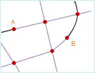
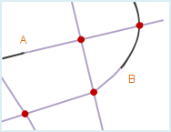
Figure 1 Figure 2 - Remove Redundant Vertices
Redundant vertices refer to multiple closely-spaced, functionally identical nodes on a line feature caused by operational errors, where only one node is valid.
When two or more nodes on a line feature have distances less than or equal to the specified fuzzy tolerance, topology processing retains one node and removes others as redundant vertices. Fuzzy tolerance can be set in the dataset's property window.
As shown in Figure 1, the distance between Points A and B on Line a is smaller than the fuzzy tolerance. During processing, Point A is removed as redundant, retaining Point B (Figure 2). Similarly, Points C and D are processed. Since Line b's endpoint C' coincides with Line a's node C without shared intersection, Line b remains unaffected. To merge Point C' and D while removing C, both Remove Redundant Vertices and Intersect Arcs must be selected.
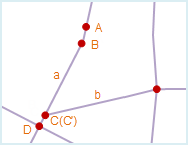
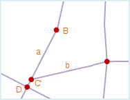
Figure 1 Figure 2 Differences between pseudo nodes and redundant vertices:
- Both operations remove unnecessary points
- Redundant vertices must be removed, while pseudo nodes require retention when meaningful
- Redundant vertices typically result from accidental double-clicking during digitization, connecting continuous line segments; pseudo nodes form during endpoint merging or snapping operations, connecting separate line features
- Redundant vertices are non-terminal nodes, while pseudo nodes are endpoints
- Remove Duplicate Lines
When two line features have all corresponding nodes coinciding (identical coordinates) or within fuzzy tolerance (disregarding direction), they are considered duplicate lines.
To prevent zero-area or micro-polygons during polygon topology construction, duplicate lines are removed during processing, retaining only one instance.
As shown in Figure 1, Line AB duplicates Line A'B' (highlighted for clarity). Post-processing, duplicate Line A'B' is removed (Figure 2).
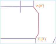
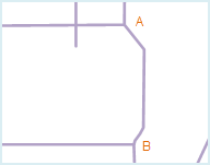
Figure 1 Figure 2 - Remove Overshoots
A dangling node is an unconnected arc endpoint, forming a dangling arc. Short overshoots refer to dangling segments below specified tolerance.
When enabled with tolerance settings, segments shorter than tolerance are removed. The tolerance must be less than 100×dangle tolerance (set in dataset properties). Zero tolerance uses default values.
As shown in Figure 1, Lines a and b contain short overshoots below tolerance, removed during processing. Line c's overshoot exceeds tolerance and remains (Figure 2).
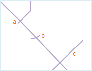
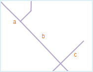
Figure 1 Figure 2 - Extend Undershoots
Long undershoots are dangling arcs where endpoints nearly reach other features. When enabled with tolerance settings, endpoints extending within tolerance to nearest features are connected.
Tolerance must be less than 100×dangle tolerance. Zero tolerance uses default values.
As shown in Figure 1, Lines a and b undershoot Line d within tolerance, thus extended. Line c's extension exceeds tolerance and remains (Figure 2).
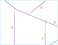
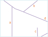
Figure 1 Figure 2 - Merge Adjacent Ends
When multiple arc endpoints lie within fuzzy tolerance, they're merged into single nodes. Fuzzy tolerance is set in dataset properties.
Note: Merging two endpoints creates a pseudo node requiring subsequent Remove Pseudo Nodes operation.
As shown in Figure 1, adjacent endpoints at Locations A and B are merged. Location A produces pseudo nodes needing further processing (Figure 2).
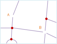
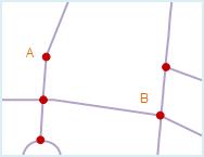
Figure 1 Figure 2 - Intersect Arcs
This operation splits intersecting lines at crossing points into connected simple arcs, preventing polygon topology errors like missing or overlapping polygons.
As shown in Figure 1, intersecting Lines a, b, and c are split at intersection points A, B, and C (Figure 2).
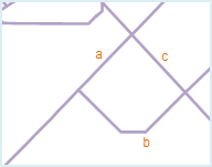

Figure 1 Figure 2 For complex scenarios requiring preserved intersections:
- Non-breaking Features: Define filter expressions via SQL Expression dialog (
 ) to exclude features from splitting. See SQL Expression Query.
 - Non-breaking Locations: Select point datasets to preserve intersections near specified points within tolerance.
Unset parameters default to full processing. Combined settings process union of excluded features and locations.
- Non-breaking Features: Define filter expressions via SQL Expression dialog (
 Notes:
- Select appropriate topology processing combinations based on data characteristics and application requirements
- Recommended to enable Intersect Arcs for optimal results
- Processing modifies source datasets directly. Backup data before operation
- Intersect Arcs creates true nodes, while Merge Adjacent Ends may produce pseudo nodes requiring subsequent removal
- Processing results depend on tolerance settings. Default values are recommended