



Function Description
The snapping function ensures that our editing work is more accurate, less prone to errors, and makes object positioning more convenient and easier. The Snapping section details how to enable layer snapping, how to use snapping, and the snapping types supported by SuperMap.
Operation Instructions
- Right-click the vector layer node in the layer manager, and click the Snappable command in the context menu that appears.
- After clicking, Snappable is activated, indicating that the layer is made snappable, meaning objects in the layer can be snapped by the mouse; otherwise, it is not snappable.
- In the Layer Properties interface, check the Snappable checkbox, and then objects in the layer can be snapped by the mouse.
 Notes:
- The Snapping icon before the vector layer node in the layer manager is also used to control whether the vector layer is snappable. You can click this button to enable or disable snapping.
- Only when the layer is both snappable and editable can the mouse snap to objects in that layer during operations such as selection and editing in the layer.
Enabling Layer Snapping
The Snappable command is used to control whether this vector layer is snappable, i.e., whether the mouse can snap to objects in this vector layer during operations such as selection and editing in the vector layer.
Using Snapping
When editing and mapping, users often need to locate specific positions, but these positions are usually not easy to accurately locate manually during actual mapping. Based on this need, SuperMap provides a powerful graphic snapping function, where the system performs intelligent snapping and positioning. During actual operation, we can freely choose the snapping type. When the snapping function is enabled, the node currently being drawn automatically snaps to edges, other nodes, or other geometric features within the tolerance.
During editing operations, users can dynamically set snapping items in the toolbar and menu bar. At the same time, you can click the Snapping Settings button in the Edit the settings group on the Edit Data tab to pop up the Snapping Settings dialog box. Users can make related settings for snapping types and snapping parameters.
Snapping Type Settings
 |
| Figure: Snapping Types |
- The Type tab is used to control the enabling and disabling of corresponding snapping types. The list below the Type tab enumerates 12 commonly used snapping relationships. For explanations and illustrations of the specific meanings of each snapping function, please refer to Supported Snapping Types. When a snapping type is checked, the corresponding snapping function is enabled; when a type is unchecked, the corresponding snapping function is disabled.
- Priority: You can set the priority of the snapping types in the list. The order of snapping types in the list determines their priority. Snapping types listed above have higher priority than those below, as shown in the figure below. Select one or more snapping types, and adjust the priority of the selected items using the buttons to the right of Priority: Top, Bottom, Up, and Down.
-

Figure: Snapping Item Priority - Enable: Check the Enable checkbox to enable all snapping types; uncheck it to disable all snapping types.
- Default: Click the Default button in the dialog box to restore the system default selected snapping types.
Snapping Parameters
The Parameters tab is used to configure snapping parameters, including snapping tolerance, angle, length, number of snapping objects, snapping length, and whether to add nodes.
 |
| Figure: Snapping Parameters |
- Snapping Tolerance
The snapping tolerance can be set in the range of 1-20, in pixels, with a default value of 15. If the set snapping tolerance exceeds 20, the system will prompt that it is greater than the maximum value. If the distance between the object to be snapped and the cursor is within the set range, the object will be snapped. As shown in the cursor positioning area diagram in the lower right corner of the dialog box, the size of the red circle (i.e., the cursor positioning area) changes with different snapping tolerance settings.
- Fixed Angle
The fixed angle can be set in the range of 0-360, in degrees, with a default value of 90. If the set fixed angle is not within the default range, the system will prompt. When drawing a line, if the angle between the segment to be drawn and other line segments equals the set angle, the system will use the fixed angle snapping icon to indicate it.
- Fixed Length
The unit of fixed length is consistent with the map unit, with a default value of 1000. If the length of the segment to be drawn equals the set length, the system will use the fixed length snapping icon to give a prompt.
- Ignorable Line Length
The ignorable line length can be set in the range of 1-120, in pixels, with a default value of 50. If the set ignorable line length range is not within the default range, the system will prompt. The ignorable line length value is the minimum length of the snapping line. When the length of the line object is less than the set value, it will not be snapped.
- Add a Node When Point Is Snapped to the Line
Check this item to insert a node at the snapping point position on the line when a point snaps to the line; uncheck it to not insert a node at the snapping position when a point snaps to the line.
- Default
Click this button to restore the snapping settings parameters to their default values.
Notes:Snapping settings are global settings. Once set, they take effect for all maps, and after restarting the program, the snapping settings from before the last closure will be saved.
Supported Snapping Types
The following uses illustrations and text to detail the specific meanings of each snapping type.
| Snapping Button | Snapping Description | Illustration |
 |
Make the currently drawn line perpendicular to other linear features (including extension lines). Illustration: The line segment being drawn is perpendicular to any existing line segment. |
 |
 |
Make the currently drawn line parallel to other linear features. Illustration: The line segment being drawn is parallel to any existing line segment. |
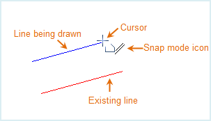 |
 |
Snap line with horizontal/vertical. Illustration: The currently drawn line is horizontal. |
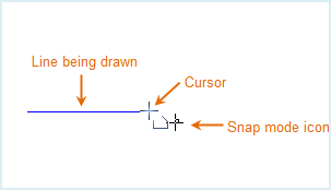 |
 |
Snap segment in fixed length. Illustration: The length of the currently drawn line segment is a fixed value. |
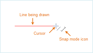 |
 |
Snap line a fixed angle to previous segment. Illustration: The currently drawn line segment forms a fixed angle with the previous segment. The fixed angle value set here is 90 degrees. |
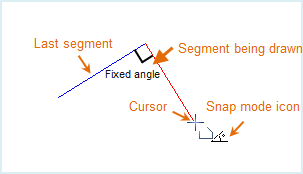 |
 |
Snap the currently drawn point to an endpoint (endpoint of a line or polygon boundary line). Illustration: Snapping to the endpoint of a line. |
 |
 |
The current mouse point forms a horizontal or vertical line with a point on another linear feature. Illustration: The virtual line connecting the mouse cursor point and any line segment endpoint is horizontal or vertical. |
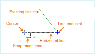 |
 |
Snap point on line. Illustration: Snapping to a line, i.e., the current mouse cursor point is on the snapped line. |
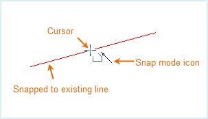 |
 |
Snap point on midpoint. Illustration: Snapping to the midpoint of a line. |
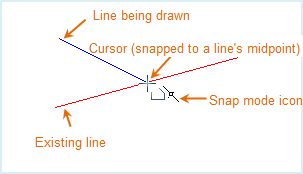 |
 |
Snap point on point. Illustration: Snapping to the midpoint of a line. |
 |
 |
Make the currently drawn point on the geometric intersection of a line and a links. Illustration: Snapping to the intersection of a line and a line. |
 |
 |
Make the currently drawn point on the extension line of other linear features. Illustration: Snapping to a point on the extension line of a line. |
 |