



Function Description
In the editable state, use the drawn polyline to update a part of a line object or a region object. The local update function can use the intersecting part of the polyline and the source object (the line object to be updated) to form a new object.
- The local update function is applicable to line layers, region layers, and CAD layers.
- When the object to be updated is not selected, the start point and end point of the drawn polyline must be on the boundary of the object to be updated. Therefore, it is recommended to enable the snapping function during operation.
- If the object to be updated is selected, you can use clip mode for updating. The drawn polyline must have at least two intersections with the object to be updated.
- The objects involved in local update can be simple objects or individual sub-objects of complex objects, but cannot be compounds.
- In the local update operation, depending on the object type to be updated, the update results will vary. The following describes updating line objects and region objects in detail.
- Object to be updated is an unselected line object (Snap mode)
As shown in the figure below, it is a schematic diagram of the local update of an unclosed and unselected line object.
Figure 1 shows the line object to be updated. It is updated using the polyline drawn in Figure 2. The start and end points of the polyline must be on the line object. The highlighted and bold segment in Figure 2 is the result of the local update.
The drawn update polyline divides the line object to be updated into three segments. After determining the start and end points of the update polyline, press the keyboard shortcut Ctrl or Shift to switch the local update result, as shown by the highlighted and bold segment in Figure 3.

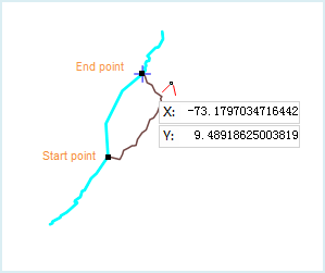
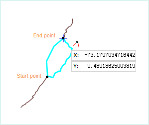
Figure 1: object to be updated Figure 2: local update operation Figure 3: switching local update result - Object to be updated is a selected line object (Clip mode)
As shown in the figure below, it is a schematic diagram of the local update of an unclosed and selected line object.
Figure 4 shows the line object to be updated. It is updated using the polyline drawn in Figure 5. The drawn polyline must have at least two intersections with the line object to be updated. The highlighted and bold segment in Figure 5 is the result of the local update.
The drawn update polyline divides the line object to be updated into three segments. After determining the start and end points of the update polyline, press the keyboard shortcut Ctrl or Shift to switch the local update result, as shown by the highlighted and bold segment in Figure 6.
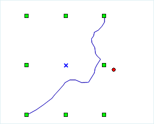
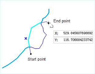
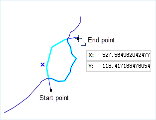
Figure 4: object to be updated Figure 5: local update operation Figure 6: switching local update result - Object to be updated is an unselected region object (Snap mode)
As shown in the figure below, it is a schematic diagram of the local update of a closed and unselected region object.
Ensure the start and end points of the update polyline are on the boundary of the region object. The preview effect of the update result is the blue area (Figure 8), and the updated region object boundary is displayed with a highlighted bold line. If you press Ctrl or Shift, the update result will automatically switch, as shown by the blue area between the highlighted bold segments in Figure 9.
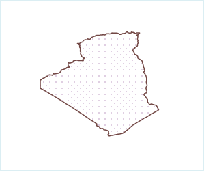
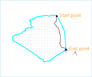

Figure 7: closed region object to be updated Figure 8: local update result 1 Figure 9: local update result 2 - Object to be updated is a selected region object (Clip mode)
As shown in the figure below, it is a schematic diagram of the local update of a closed and selected region object.
The start and end points of the update polyline can be inside or outside the boundary of the region object. The drawn polyline must have at least two intersections with the boundary of the region object. The preview effect of the update result is the blue area (Figure 11), and the updated region object boundary is displayed with a highlighted bold line. If you press Ctrl or Shift, the update result will automatically switch, as shown by the blue area between the highlighted bold segments in Figure 12.
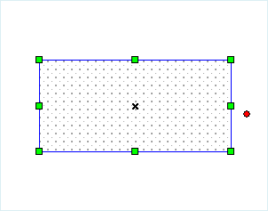
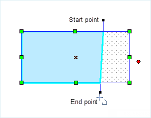
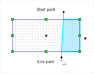
Figure 10: closed region object to be updated Figure 11: local update result 1 Figure 12: local update result 2
- Object to be updated is an unselected line object (Snap mode)
Function Entry
- Edit Data tab -> Object Editing group -> General editing -> Trimming -> Local update
Operation Instructions
- In the Layer Manager, set the layer to the editable state.
- In the Edit Data tab, in the General editing drop-down menu, click the Local update button in the Trimming group to perform the local update operation. At this time, a polyline cursor
 will appear on the map.
 - Local update has two operation modes: snap mode and clip mode. The operation method differs depending on whether the object to be updated is selected. If the object to be updated is not selected, only snap mode can be used for updating. If the object to be updated is selected, either snap mode or clip mode can be used.
- Snap mode: Move the polyline cursor to the boundary of the line object or region object to be updated. The drawn start and end points must be on the boundary of the object to be updated. If they are not on the boundary, the output window will prompt: "The point should be in the line when updating with capture mode. Please select an object if you want to update with clip mode." The start point needs to be redrawn. If the start point of the drawn polyline is snapped to the line, it must be snap mode.
 Notes:
When using snap mode, you need to enable the Point Snapping to Lines function in Snapping Settings first.
- Clip mode: Select the object to be updated. The drawn start point can be on the boundary of the object to be updated or not, but the drawn polyline must have at least two intersections with the boundary of the line object or region object.
- Snap mode: Move the polyline cursor to the boundary of the line object or region object to be updated. The drawn start and end points must be on the boundary of the object to be updated. If they are not on the boundary, the output window will prompt: "The point should be in the line when updating with capture mode. Please select an object if you want to update with clip mode." The start point needs to be redrawn. If the start point of the drawn polyline is snapped to the line, it must be snap mode.
- Continue to draw the polyline. When the drawn point snaps to the object to be updated, the updated shape will be highlighted automatically. The currently drawn polyline will divide the boundary of the object to be updated into multiple segments. Hold down the Ctrl key to switch the selection of the boundary to update.
- Right-click the mouse to confirm updating with the currently drawn shape, completing the local update operation.