



Function Description
In the Edit Data tab, under the Object Editing group, the function to generate a chamfer is provided. Similar to fillet, chamfer connects two objects. Fillet connects them with a smooth arc, while chamfer connects them with a straight corner.
The adjacent endpoints of two line segments are extended or trimmed, and finally connected to form a chamfer. As shown in the figure below, when both chamfer distances are 0, the two lines will be trimmed or extended until they intersect. When both chamfer distances are non-zero, the two line segments are extended according to the specified distances, and then the two lines are connected.
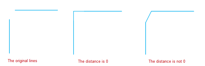
- The Chamfer button is only available when two line segments are selected in an editable layer, meaning the function only applies to the two selected line segments.
- The objects involved in generating a chamfer must be simple line objects, and their extension lines must have exactly one intersection. The operation will fail if the two lines are parallel or collinear.
- After the operation, the source lines may be extended or trimmed, but their attributes remain unchanged.
- Parameter description for chamfer distance: When generating a chamfer, there are strict restrictions on the two distance parameters. The valid range for a distance parameter is from 0 to the distance from the intersection point of the two lines to the farthest endpoint of the corresponding line. For parameters exceeding this length, the application will display an error message.
- Although a chamfer operation can be performed on intersecting lines, it has no obvious geometric meaning, so this case is not described in detail.
Function Entry
- Edit Data tab -> Object Editing group -> Line editing -> Endpoint editing -> Chamfer
Operation Instructions
- Set the layer of the line segments to be chamfered as the current editable layer.
- Select two line segment objects (non-parallel) in the layer simultaneously.
- In the Edit Data tab, click the Chamfer button in the Endpoint editing group under the Line editing drop-down menu to open the Chamfer Settings dialog. In the pop-up dialog, enter the distances to the first line and the second line respectively. By default, both distances are 0, which directly connects the two lines at their intersection.
- Set whether to trim the source objects. Checking this option trims the source objects after the operation; otherwise, the original objects are preserved.
- A real-time preview of the chamfer effect is displayed on the map. Click the OK button to execute the chamfer operation according to the user's settings.
Parameter Description
First Line Chamfer Distance: The distance from the intersection point of the extension lines of the two lines to the nearest endpoint of the first line after the first line is trimmed or extended. As shown in the right figure below, the first line chamfer distance is 100.
Second Line Chamfer Distance: The distance from the intersection point of the extension lines of the two lines to the nearest endpoint of the second line after the second line is trimmed or extended. As shown in the right figure below, the second line chamfer distance is 50.
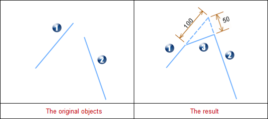 |
- 1 indicates the first line, 2 indicates the second line, and 3 indicates the newly generated chamfer line.
- The first line is trimmed, and the second line is extended.
 Notes:
- Description of Valid Range for Distances
The minimum value of the distance is 0; the maximum value is the distance from the intersection point to the farthest endpoint of each line. If the value is greater than this, the output window will prompt: The entered distance is too large, chamfer failed!.
If the distance is 0, the chamfer line will have some special changes. See the table below for illustrations and descriptions.
First Line Chamfer Distance Second Line Chamfer Distance Illustration Description 0 Non-zero 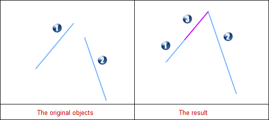
The first line is extended to the intersection point of the two lines. The second line is trimmed. The newly generated chamfer line lies on the extension of the first line in the result, and its length equals the first line's chamfer distance. Non-zero 0 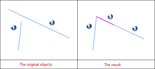
The first line is trimmed. The second line is extended to the intersection point of the two lines. The newly generated chamfer line lies on the extension of the second line in the result, and its length equals the second line's chamfer distance. 0 0 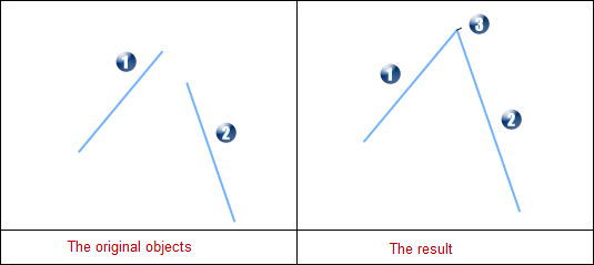
Both the first and second lines are extended to the intersection point. The newly generated chamfer line is located at the intersection point and is a virtual line of length 0. - Direction Description
After the operation, the direction of the source lines may change. See the figure and description below.
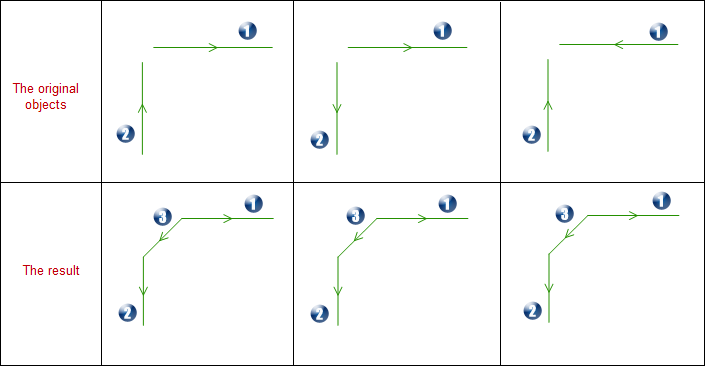
- 1 indicates the first line, 2 indicates the second line, and 3 indicates the newly generated chamfer line.
- The direction of the newly generated chamfer line is from the first line to the second line.
- The direction of the first line changes to be opposite to that of the newly generated chamfer line.
- The direction of the second line changes to be the same as that of the newly generated chamfer line.