Central Point Adjustment
Feature Description
The Central Point Adjustment function enables the connection of adjacent lines. It performs adjustment calculations on all nodes within the specified range (determined by circular selection). The adjustment result generates a new node (positioned at the calculated centroid of all selected nodes), deletes all circled nodes, and connects line objects at the new node.
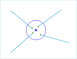
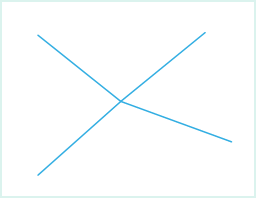
As shown in the following figure, when selecting endpoints of four adjacent lines (nodes within blue circles), the adjustment operation will delete all selected endpoints, compute a new node through adjustment, and connect it to remaining nodes on the four lines.
 |
 |
| Nodes Selected for Operation | Result of Central Point Adjustment |
- The Central Point Adjustment function applies to line layers and CAD layers.
- When the selection range is large, this operation will not process line objects entirely within the temporary circular drawing area.
 Notes:
- The connection is made at the nodes only and does not form a single object.
- Central Point Adjustment only adjusts endpoints of line objects, not all selected nodes.
Feature Entry
- Features Tab->Feature Editing Group Dropdown->Central Point Adjustment.
Steps
- When the layer is editable, click Central Point Adjustment in the Gallery control of the Feature Editing group under the Features tab to execute the operation.
- Move the cursor to the map, where the prompt "Please circle select vertices for adjustment" appears. Draw a temporary circle on the map to encompass nodes requiring adjustment.
- Left-click to perform adjustment on selected nodes.
- Right-click to cancel the current operation.


