


End-To-End Connection Line
Function Description
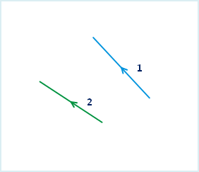
End-to-End Connection Line: Connect the start point and end point sequentially according to the order of the lines (the selection order or SMID order of the line objects). That is, connect the end point of the first line object to the start point of the second line object, the end point of the second line to the start point of the next line, and so on. The direction of the generated line after connection is the same as that of the first line object.
- The joint line object function is applicable to 2D line layers and CAD layers.
- The joint line object function is only available when line objects are selected.
- This operation does not apply to complex objects and compounds. For an introduction to object types, refer to Overview of Objects.
- Explanation of the line object order. When connecting objects end-to-end, the order of the line objects to be joined needs to be determined to define the direction of the line. The application provides two ways to determine the order of the line objects to be connected. One is to select multiple line objects while holding the Shift key, and the line objects will be connected in the selection order. The other is to box-select with the mouse, and the line objects will be connected in ascending order of their SMID.
Function Entry
- Edit Data Tab -> Object Editing Group -> Line Editing -> Connect and Break -> End-to-End Connection Line
Operation Instructions
- In the editable state of the layer, select one or more line objects to be connected.
- In the Edit Data tab, from the Line Editing dropdown menu, click the End-to-End Connection Line button in the Connect and Break group to perform the line connection operation.
- The End-to-End Connection Line dialog box appears. In this dialog box, set the properties of the new object after the connection.
In the End-to-End Connection Line dialog box, you can either set the operation mode for each field individually, or select multiple fields at once to unify the settings. Below is an explanation of this dialog box.
- Edit Layer: The edit layer dropdown lists all editable layers in the current map. You can click the dropdown arrow on its right to select the layer to operate on.
- Field List Area: This area lists all non-system fields and editable system fields in the current editable layer, including field name, type, and the operation mode for the new object's fields after the connection operation. The default uses the field attributes of the first object.
- Operation Mode Setting Area: Provides four operation modes.
- Null: Indicates that the value of this field in the new object after connection is empty.
- Sum: Indicates that the value of this field in the new object after connection is the sum of the corresponding field values of each connected object.
- Weighted Mean: Indicates that the value of this field in the new object after connection is the weighted mean of the corresponding field values of all connected objects. A weighting field needs to be specified. If no weighting field is selected, the simple average is calculated, i.e., adding the selected field values of all source objects and dividing by the number of source objects.
- Save Geometry: Indicates that the value of this field in the new object after connection is the same as the value of this field in a currently selected object. You can click the dropdown arrow on the right to select the object properties value to be used for the new object.
- Click the OK button to complete the line object connection operation.
 |
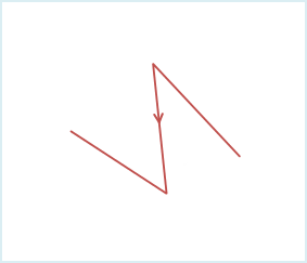 |
| Figure 1: Line objects before connection | Figure 2: End-to-end connection line |