Drawing Orthogonal Polygon
Feature Description
An orthogonal polygon is a type of polygon commonly used in housing planning and design. It is often employed to represent regular buildings or models with orthogonal structures.
Feature Entry
- Features tab -> Feature Drawing group -> Orthogonal Polygon.
Steps
Drawing Orthogonal Polygon
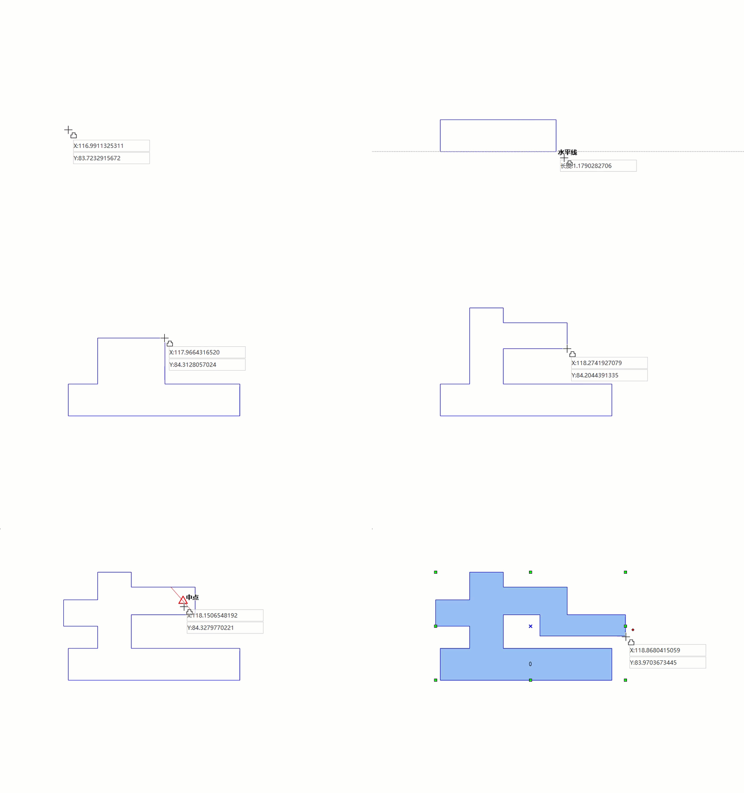
- In the Features tab's Feature Drawing group, click the Orthogonal Polygon drop-down button and select Orthogonal Polygon from the menu. The cursor will change to an orthogonal polygon shape.
- Move the mouse to the map. The parameter input boxes will display real-time coordinates as the mouse moves. Enter the starting coordinates of the first edge in the parameter input boxes (use Tab to switch between boxes) and press Enter to confirm the starting position.
- Move the mouse to see real-time length and angle relative to the X-axis displayed. Input length and angle values in the parameter input boxes (use Tab to switch) and press Enter to complete the first edge.
- A blue orthogonal line will appear perpendicular to the first edge. Move along the orthogonal direction (90° or 270°) and input the second edge's length in the parameter input box. Press Enter to confirm:
 Notes:
Right-clicking at this point will end the drawing and generate a rectangle.
- Continue drawing subsequent edges using the same method.
- Right-click to finish the drawing operation.
Drawing New Orthogonal Polygon
- In the Features tab's Feature Drawing group, click the Orthogonal Polygon drop-down button and select New Orthogonal Polygon. The cursor will change to an orthogonal polygon shape.
- Move the mouse to the map. Input the starting coordinates of the first edge in the parameter input boxes (use Tab to switch) and press Enter.
- Move the mouse to see real-time length and angle from the starting point. Click left mouse button or input length/angle values in parameter boxes to complete the first edge's endpoint.
- A temporary orthogonal rectangle will appear as the mouse moves. Input length value in the parameter box and press Enter to confirm the temporary rectangle.
- Move the mouse to a new position and click left button (or input coordinates) to define the first edge of the next temporary rectangle. Move and click/input coordinates again to define the diagonal corner point. The application will automatically connect existing and new rectangles into a temporary orthogonal polygon.
- Right-click to generate the final orthogonal polygon. Repeat the previous step for more complex shapes.

 Notes:
Both Orthogonal Polygon and New Orthogonal Polygon commands can create orthogonal polygons, but differ in drawing methods. The former requires multiple edge length inputs, while the latter uses diagonal corner coordinates.


