


Function Description
Parallel command is used to draw parallel lines with two sub-objects. In practical applications, parallel lines are mainly used to describe relatively regular parallel polylines, such as railways, roads, power lines, etc. The application provides By Inputting Coordinate Values and By Inputting Length and Angle two ways to draw parallel lines.
It also supports the Drawing Multiple Parallels function. By specifying the number of parallel lines to be drawn and the width of each parallel line, it meets the needs of drawing parallel lines in different application scenarios.
It supports increasing or decreasing the width between parallel lines at any time during the drawing process according to the setting step value, making it convenient for users to draw a continuous parallel line with varying widths.
Function Entrance
- Features tab -> Objects group -> Line -> Line -> Parallel/Parallel (length, angle)/Multiple Parallels.
Operation Instructions
Drawing Parallel Lines
Drawing Parallel Lines by Inputting Coordinate Values
- In the Features tab's Objects group, click the Line drop-down button, select the Parallel command, and the parallel line cursor appears. Simultaneously, the Setting Step Value dialog box pops up.
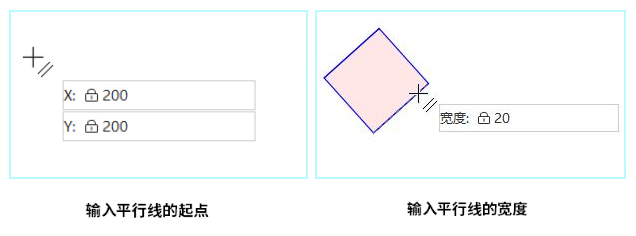
- Set the Starting Point Position: Move the mouse to the map. You can see that as the mouse moves, the coordinate values of the current mouse position are displayed in real-time in the following parameter input box. In this box, input the coordinate values of the parallel line's starting point (you can switch between the two input boxes by pressing the Tab key) and then press Enter to confirm the starting position of the parallel line.
- Set the Parallel Line Width: Move the mouse and input the width (length) of the parallel line in the following parameter input box, then press Enter to execute the input. Move the mouse, and you can see that the width of the parallel line has been determined.
- In the map, the point coordinates X, Y, and width value of the mouse position are displayed in real-time (you can switch between the three parameter input boxes by pressing the Tab key). Press Enter to complete the coordinate values of the next node of the parallel line.
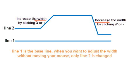
- It supports increasing the parallel line width by pressing the Q or + key and decreasing it by pressing the W or - key. The parallel line consists of two line objects. As shown in Figure 1 below, using line ① as the reference, the width increased or decreased is between line ② and line ①. It supports setting the step growth method and length in the Setting Step Value dialog box:
- Setting Step Value: You can set the step value in two ways: By Percentage Growth and By Fixed Length Growth. Users can choose according to their needs.
- By Percentage Growth: The default is 20%, meaning that each time the step is increased or decreased, the proportion is 20% of the current width. For example, if the current width is 100 meters, after increasing once with the Q key, the current width becomes 120 meters. When increasing again, it is based on the width of 120, increasing by 20%, so the width becomes 144 (120 * 20%). And so on, always growing by a percentage of the current width.
- By Fixed Length Growth: Set a fixed length as the growth step. The default is 2 meters, meaning that each time the step is increased or decreased, it is by 2 meters. For example, if the current width is 100 meters, after decreasing once with the W key, the current width becomes 98 meters. Always increase or decrease the width value by the input fixed value.
- Repeat steps 4-6 to complete the drawing of other segments of the parallel line. Users can change the drawing direction of the parallel line by using the shortcut Ctrl+R. The program will automatically locate the other endpoint position of the parallel line, allowing users to switch the drawing direction at any time.
 Notes:
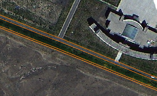
When drawing continuously with a fixed width, the parallel lines remain parallel. When continuously increasing or decreasing the road width, the parallel lines will no longer remain parallel. For example, when vectorizing the road shown in the figure below, the initial width of the road is 6m, the middle width is 9m, and the last segment is a junction with uneven width. During the drawing process, the road from 6m to 9m is drawn with a regular fixed width, which can remain parallel. However, from 9m to 30m, the width continuously increases in a non-continuous manner, so the drawn double lines are non-parallel.
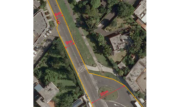
Vectorized Road - Click the right mouse button to end the parallel line drawing operation.
Drawing Parallel Lines by Inputting Length and Angle
- In the Features tab's Objects group, click the Line drop-down button, select the Parallel (length, angle) command, and the parallel line cursor appears. Simultaneously, the Setting Step Value dialog box pops up.
- In the map, Set the Starting Point Position and Set the Parallel Line Width. The operations are the same as steps 2-3 in Drawing Parallel Lines by Inputting Coordinate Values.
- After determining the starting point and width, the map displays in real-time the length of the line connecting the mouse position and the starting point, its angle with the positive X-axis direction, and the width value. In the parameter input box, input the length and angle values (you can switch between the two parameter input boxes by pressing the Tab key), then press Enter to confirm and determine the length of the parallel line.
- It also supports Setting Step Value, and the setting method is the same as in Drawing Parallel Lines by Inputting Coordinate Values.
- Repeat step 3 to complete the drawing of other segments of the parallel line. Click the right mouse button to end the parallel line drawing operation.
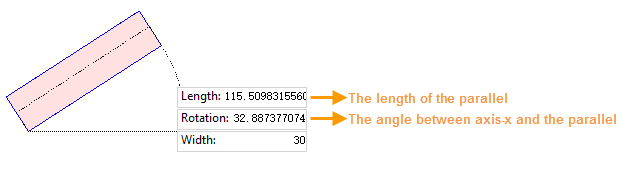
Input the Length and Angle of the Parallel Line
Drawing Multiple Parallels
Drawing Multiple Parallels means that users can specify the number of parallel lines to be drawn simultaneously and set the width of each parallel line separately. For example, during image vectorization, it is common to encounter带状用地 such as roads, ditches, and forest lands distributed and arranged simultaneously. At this time, the Multiple Parallels function can be used to draw three parallel lines for roads, ditches, and forest lands at once. Drawing multiple parallel lines at once saves users' drawing time and greatly improves work efficiency. The following provides a detailed operational description of this example:
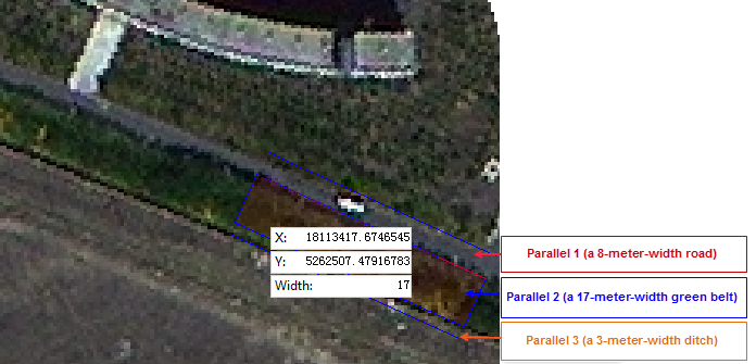 |
| Multiple Parallels Settings |
 |
| Multiple Parallels Drawing Result |
- In the Features tab's Objects group, click the Line drop-down button, select the Multiple Parallels command, and the Parameters dialog box pops up. Set the number of parallel lines to be drawn.
- Click the OK button, and the Setting Step Value dialog box pops up. Simultaneously, the mouse pointer in the map switches to the parallel line drawing state. Set the starting point position of the parallel line.
- Use Ctrl+Q or Ctrl+W to switch between parallel lines, and set the width of each parallel line in turn. When a parallel line is filled with red, it indicates that the current parallel line width can be adjusted.
- In the map, the point coordinates X, Y, and width value of the mouse position are displayed in real-time (you can switch between the three parameter input boxes by pressing the Tab key). Press Enter to complete the coordinate values of the next node of the parallel line. It also supports increasing the parallel line width by pressing the Q or + key and decreasing it by pressing the W or - key.
- Repeat steps 3-4 to complete the drawing of other segments of the parallel line. The drawing process is the same as Drawing Parallel Lines. Simultaneously, you can change the drawing direction of the parallel line by using the shortcut Ctrl+R.
- Click the right mouse button to end the parallel line drawing operation.
Notes:During the parallel line drawing process, if the step length is adjusted in the Setting Step Value dialog box and then you return to the map to continue drawing, the shortcuts for increasing or decreasing the width may not respond. In this case, simply move the map to refocus the window on the parallel line drawing window to resolve the issue.
Shortcut Keys for Drawing Parallel Lines
| Shortcut Key | Function Description |
| W, - | Decrease step length |
| Q, + | Increase step length |
| Ctrl+R | Reverse parallel line |
| Ctrl+Z | Undo one step |
| Ctrl+P | Open the Setting Step Value dialog box |
| Ctrl+E | Display the current parallel line with adjustable width |