


DEM Construction
DEM (Digital Elevation Model) is commonly used to represent terrain features. It mainly describes the spatial distribution of geomorphological characteristics in a region, generated through interpolation or simulation calculations using elevation measurement points (or sampled elevation points from contour lines). The terrain construction function provided by SuperMap generates DEM data from point or line data through interpolation, resulting in a raster dataset.
The application provides three methods for terrain construction:
- Generate DEM from point data (elevation points), similar to interpolation algorithms.
- Generate DEM from line data (contours) to enhance terrain features like ridges and valleys.
- Combine point and line data for joint construction. This method produces more three-dimensional DEM by incorporating feature point elevation information such as hilltops, depressions, and ridge/valley points.
In practice, when using line data for construction, the application extracts points from line objects before interpolating to build terrain.
Understanding the following concepts will help create better terrain model data:
- Source Dataset and Elevation Field
Source dataset refers to one or multiple point/line datasets used for terrain construction. All source datasets must contain an elevation field providing terrain characteristic information.
- Interpolation Type
The application offers three interpolation methods: TIN (Triangulated Irregular Network), IDW (Inverse Distance Weighted), and Kriging.
- IDW estimates cell values by averaging nearby discrete points, providing fast computation with simple implementation.
- TIN first creates a TIN model from line datasets, then generates terrain using optional extremum points and lake information. Suitable for small areas with complex terrain details.
- Kriging uses ordinary kriging principles, ideal for large-scale terrain modeling with simple data structures.
- Duplicate Point Handling
When duplicate points (line nodes) with conflicting elevation values exist, two processing methods are available: use the first occurrence value or apply statistical values (average, max/min, mode, median).
- Resampling Distance
This parameter filters dense nodes in line data before TIN generation to improve performance. Available only when using line datasets with TIN interpolation. Default value 0.0 means no resampling. For details see: Line Object Resampling.
- Elevation Scale Factor
Controls elevation stretching intensity. Larger values create more exaggerated terrain. A factor of 1 indicates no stretching (original height).
- Lake Polygon Data and Elevation Field
Lake region datasets store water body information where each polygon represents a lake. An elevation field specifies water surface elevation values for corresponding raster areas. This can also represent depressions or glaciers requiring special processing.
- Range Data
2D polygon data defining the terrain's geographic extent. Two usage modes:
- Clip dataset: Only generates terrain within specified polygons.
- Erase dataset: Assigns no-data values to areas within specified polygons (TIN interpolation only).
- Without range data, terrain extent equals the union of source dataset bounds.
- Result Data
Configure result parameters including target datasource, dataset name, encoding type, pixel format, and resolution. The application automatically calculates row/column counts and estimates dataset size (in MB).
DEM Lake Cutting
Real-world terrain may contain lakes, rivers, reservoirs, or glaciers. By specifying polygon data with elevation information, terrain construction can incorporate these features.
Two lake-cutting methods are available:
- Direct elevation assignment: Set lake area elevation to a specified value.
- Field-based elevation: Use values from a specified elevation field in polygon data.
Below illustrates DEM lake-cutting effects:
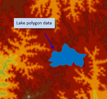 |
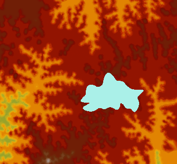 |
|
| Terrain with lake overlay | DEM after lake cutting |