


Regardless of the layer type (vector, raster, or image), you can set the layer's transparency, order, visible scale, and filter display objects, among other properties.
Setting Layer Transparency
Transparency is a display property of a layer and can be set in the numeric adjustment box Transparency: within the Layer Properties panel.
The numeric adjustment box for transparency allows you to set the degree of transparency for the current layer. You can also directly input a transparency value to preview the results in real time. The default transparency value is 0, meaning the layer is completely opaque. As the value increases, the layer becomes more transparent; when the transparency value is set to 100, the layer becomes completely transparent. The transparency value range is an integer between 0 and 100.
Adjusting Layer Order
The stacking order of layers directly affects the map display effects. There are two general rules for the stacking order of map layers:
- According to the object's map bounds, from top to bottom: small -> medium -> large;
- According to the layer type, from top to bottom: text to point -> line to region.
 Notes:
The above stacking order rules are just general recommendations; depending on different map production needs, there may be other ways to sort layers.
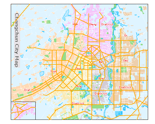
The following two maps show the map effects before and after sending a specific layer (RoadLine) to the bottom. From these two maps, the importance of layer stacking order for map display is clearly evident.
 |
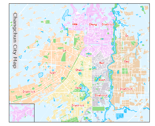 |
| Map display effects before layer adjustment | Map display effects after layer adjustment |
From the image above, it can be seen that a line layer has "disappeared" from the map. It has not been removed but has been moved to the bottom layer and sent to the back for display.
The layer order can be adjusted mainly through the following two methods:
Notes:Direct dragging requires setting the layer node to be draggable. The Layer Control drop-down menu in the layer manager toolbar -> Layer nodes can be dragged controls whether the layer order can be changed by dragging.
- Using Layer Control
Procedure:
- If there is an opened map in the current workspace, open the Layer Control dialog box through one of the following steps.
- In the layer manager, click the layer control button;
- In the layer manager, right-click any layer and select the Layer Control command.
- In the Layer Control dialog box, after selecting one or more layers, adjust the layer order using toolbar buttons such as bring to front, move up, move down, and send to back. For detailed information about layer control, please refer to Layer Control.
- If there is an opened map in the current workspace, open the Layer Control dialog box through one of the following steps.
- Direct Dragging
Procedure:
- In the layer manager, select one or more layers.
- Drag the selected layers to the target position.
- Release the mouse button.
Layer Blend Mode
Blend Mode is used to set the overlay method between two layers. It calculates the color of the upper layer combined with the lower layer, resulting in different shading effects depending on the selected mode.
The provided modes are as follows:
| Mode Category | Mode Name | Description |
| Normal Mode | Normal | Does not change the layer colors. This is the default blend type. |
| Darken | Darken | Compares the layer color with the lower layer color and selects the minimum RGB values from both layers as the final rendering effect color. |
| Multiply | Multiplies the layer color with the lower layer color, usually resulting in a darker final rendering effect color. | |
| Color Burn | Darkens the color of the lower layer; white remains unchanged. | |
| Linear Burn | Adds the layer color to the lower layer color and then subtracts the value 1. | |
| Lighten | Lighten | Compares the layer color with the lower layer color and selects the maximum RGB values from both layers as the final rendering effect color. |
| Screen | Multiplies the inverse of the layer and the lower layer's white areas. | |
| Color Dodge | Reduces contrast between the layer and the lower layer, increasing the brightness of the lower layer. Black remains unchanged. | |
| Linear Dodge (Add) | Adds the brightness of the layer to the lower layer; black remains unchanged. | |
| Contrast | Overlay | Multiplies areas in the lower layer with a color value less than 0.5 with the blend layer; areas greater than 0.5 use the screen mode for the blend layer. |
| Soft Light | Algorithm is the same as the overlay mode but reduces the color contrast of the layer. | |
| Hard Light | Areas with layer color values less than 0.5 are multiplied with the lower layer; areas greater than 0.5 use the screen mode. | |
| Vivid Light | A combination of color dodge and color burn. | |
| Linear Light | Areas where the blend layer color brightness is higher than 0.5 become brighter, and areas lower than 0.5 become darker. | |
| Pin Light | If the current layer color is lighter than 50% gray, pixels darker than the current layer color are replaced; if the current layer color is darker than 50% gray, pixels lighter than the current layer color are replaced. | |
| Difference | Difference | Subtracts the lower layer's color value from the upper layer's color value, then divides the result by 2, and finally adds the lower layer's color value back. This results in an effect where the upper layer's color is the opposite of the lower layer's color. |
| Subtract | The lower layer's color minus the upper layer's color yields the subtracted color. |
Notes:When the map layer blend mode is set to multiply, it is not recommended to enable the tile background transparency when generating raster tiles, otherwise, tile display exception (blank map) may occur.
Setting Fill Mode
Fill mode is used to control the drawing method of symbols, supporting global mode and object mode, enriching the expression of symbols on the map.
Application Example
Case Description: Taking the fill mode for all prefecture-level cities in Sichuan Province as an example, you can set the symbol mode for region objects to either global mode or object mode to enrich symbol expression.
Data Description: Region dataset.
Main Steps
- Select the region layer that needs symbols in the layer manager. In the Styles tab -> Fill Style group -> Symbols drop-down box, choose the desired symbol style.
- Select the region layer in the layer manager that needs the fill mode set, right-click -> select Layer Properties.
- In the Layer Properties window, under Display Control -> Fill Mode, you can choose Global Fill or Object Fill.
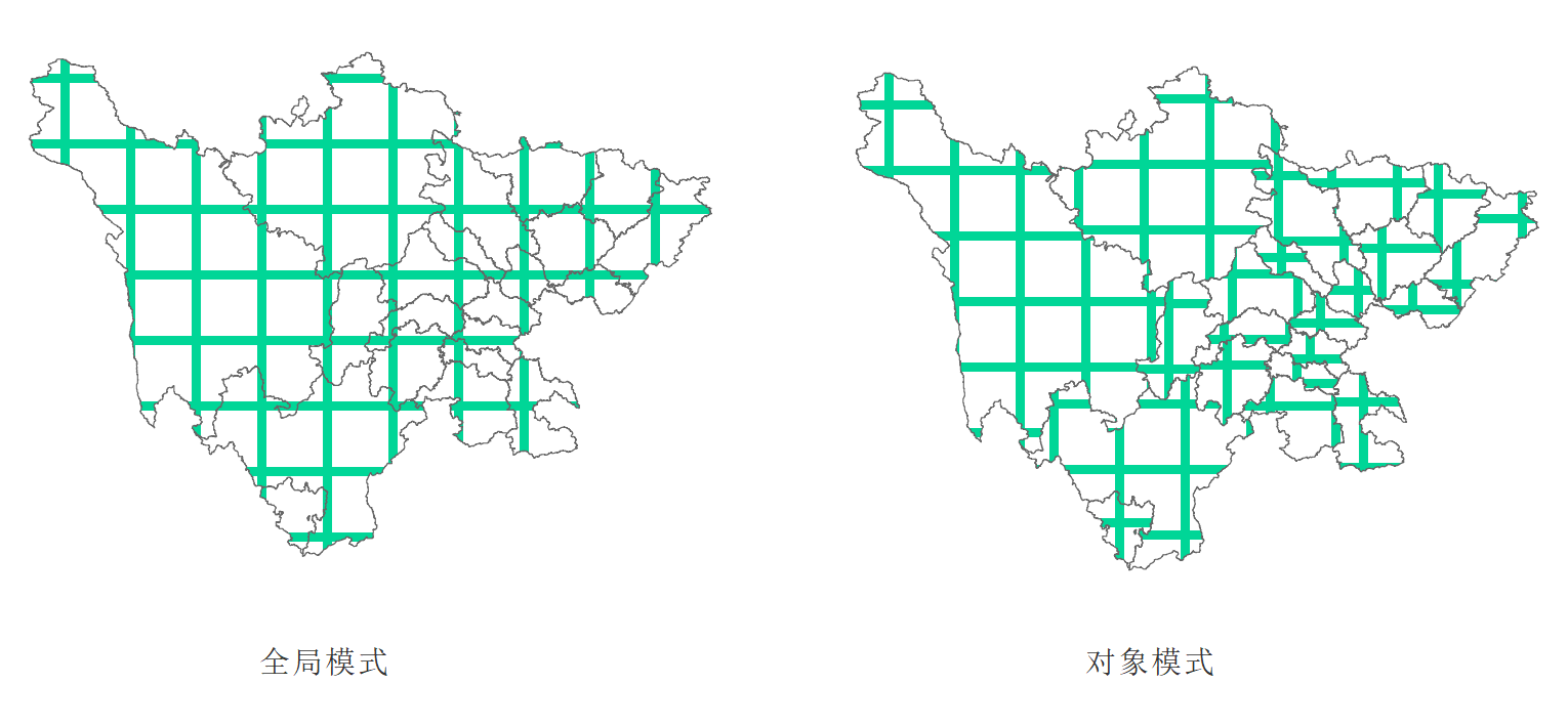
- Depending on the selected fill mode, the resulting effects will differ, as shown below:
- Left image Global Mode: Drawing starts from the top-left corner of the entire layer, making the symbols fill according to the whole layer.
- Right image Object Mode: Drawing starts from the top-left corner of each individual object, using the symbols to fill each object in the layer separately.
Notes:For CAD Datasets, which contain point, line, and region objects, the fill mode is only effective for the region objects within them.
Setting Layer Visible Scale Range
Filter objects within a layer by setting the visible scale in layer properties or by setting a filter.
Minimum Visible Scale
Minimum Visible Scale: The combo box is used to set the minimum visible scale for the current layer. After setting the layer's minimum visible scale, if the map's scale is smaller than this set minimum visible scale, the layer will become invisible.
Maximum Visible Scale
Maximum Visible Scale: The combo box is used to set the maximum visible scale for the current layer. After setting the layer's maximum visible scale, if the map's scale is greater than or equal to this set maximum visible scale, the layer will become invisible.
Notes:The right drop-down button provides different scale options depending on the situation:
- If the current map has fixed scales set, the drop-down button provides fixed scale options.
- If the current map does not have fixed scales set, the drop-down button provides eight basic scale options from 1:5000 to 1:1,000,000.
- If you have customized a scale value in the numeric adjustment box to the right of Maximum/Minimum Visible Scale, the drop-down button will record your customized value for easy reuse, in addition to the options from the previous two cases.
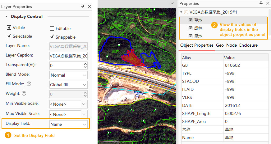
Display Field
Used to set the display field for vector objects in the properties panel. After setting, when you select a vector object on the map, you can intuitively view the attribute value of the specified display field in the object properties panel, making it easier to distinguish object categories directly from attributes. By default, the 'name' field in the layer is used; if there is no 'name' field, a text field is used; if there is no text field, the SmID field is used.
- If an invalid expression field is set, it will display as an invalid value "Null" when viewed in the object properties panel.
Display Filter
Filter Expression: Used to set the display filter for the current layer, filtering which objects in the layer can be displayed and which cannot. This allows users to display features of interest and filter out temporarily unnecessary ones.
Users can input an SQL expression as a filter in the Display Filter text box and press Enter to apply the layer filter, making objects that satisfy the filter visible in the layer. Users can also click the button to the right of the text box to open the SQL Expression dialog and construct a filter expression. After setting, click the OK button to apply the layer filter, making objects that satisfy the filter visible.
Click the Join Attribute Table... button to open the "Join Attributes" dialog. Connect to an external table through join fields, and then filter the display of layer content by constructing a filter involving fields from the external table.
Related Topics
Setting Vector Layer Properties