


Region to Line
Function Description
Convert the boundary or center line of the selected region to a line object, and save it to the CAD dataset. When converting a region object to a line object, two conversion methods are supported: boundary line and center line, as shown in the following figures:
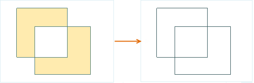 |
| Figure 1: Convert Region Boundary to Line Object |
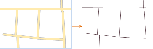 |
| Figure 2: Convert Region Center Line to Line Object |
Function Entrance
- Edit Data Tab -> Feature Editing Group -> Type Conversion -> Region to Line
Operation Instructions
- Open the region dataset to the map. With the current region layer selectable, select one or more region objects.
- In the Edit Data tab, click the Region->Line button in the Type Conversion drop-down menu. The Region->Line dialog box will pop up.
- In the dialog box, select the target datasource and dataset to store the newly generated line object. There are two ways to save the result data: Save to an existing dataset or create a new line dataset to save it. The parameters in the dialog box are as follows:
- Target Datasource: Set the datasource where the result dataset will be saved.
- Target Dataset: Select an existing line or CAD Dataset to store the newly generated line object.
- New Dataset: Check the New Dataset checkbox, set the name of the new dataset, and save the newly generated line object to the newly created line dataset. If this checkbox is not checked, the newly generated line object will be stored in the target dataset, and its property fields will also be appended to the target dataset's attribute table.
- Region to Line Type: Click the drop-down button on the right side of the combo box to select the type of region-to-line conversion. Two conversion methods are provided: Extract the boundary line and Extract the center line:
- Extract the boundary line: This conversion type refers to converting the boundary line of a region object into a line object.
- Extract center line: This conversion type refers to converting the center line of a region object into a line object. When selecting the extract center line method, you need to set the maximum width and minimum width values. For region objects with widths between the minimum and maximum values, their center lines are extracted; region objects with widths less than the minimum width do not have their center lines extracted; region objects with widths greater than the maximum width have their boundary lines extracted. For specific details, please refer to the Faces Extract Centerlines page.
- Delete Source Object: If the selected region object layer is editable, you can check the Delete Source Object checkbox to delete the selected objects from the source dataset.
- Click the OK button to complete converting the region object to line features.
 Note:
Note:- One region object generates one line object; a composite region object generates a composite line object.
- Compounds composed of multiple regions in CAD are not supported for conversion to line objects through this function.