


Function Description
The central point adjustment function enables the connection of adjacent lines. During central point adjustment, all nodes within the adjustment range (determined by circle selection) are adjusted through calculation. The adjustment result will generate a new node (the location of the new node is the center point obtained by adjusting all nodes within the range), delete all selected nodes, and join line objects at the new node.
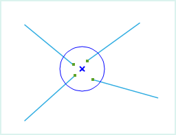
As shown in the figure below, select the endpoints of four adjacent lines (nodes within the blue circle) and perform the adjustment operation on them. The result of the adjustment is to delete all selected endpoints of the four line objects, calculate a new node through adjustment, and connect it to the other nodes on the four lines respectively.
 |
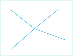 |
| Circle Select Nodes for Operation | Central Point Adjustment Result |
- The central point adjustment function is applicable to line layers and CAD layers.
- When the circle selection range is large, the central point adjustment operation does not process line objects that completely fall within the temporarily drawn circle.
 Notes:
- The connection is only at the nodes and does not form a single object.
- Central point adjustment only adjusts the endpoints of line objects, not all selected nodes of line objects.
Function Entry
- Edit Data tab -> Feature Editing group -> Line editing -> Endpoint editing -> Central Point Adjustment
Operation Instructions
- When the layer is editable, in the Edit Data tab, click the Central Point Adjustment button in the Endpoint editing group under the Line editing dropdown menu to perform the point adjustment operation.
- Move the mouse to the map, and a prompt "please circle select vertices for adjustment" appears. Draw a temporary circle on the map so that the nodes involved in the adjustment operation are just within the circle.
- Click the left mouse button to perform the adjustment operation on the selected nodes.
- Click the right mouse button to cancel the current operation.