


After executing the Validate Topology function, you can locate problematic objects through the Topology Error Details panel. Click any error record in the Error List, and the corresponding object will be highlighted in blue on the current map. Below are detailed handling recommendations for common topology errors categorized by error number.
Common Error 1: ID = 9
-
Errors
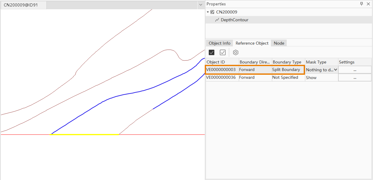
For all line objects, when boundary direction (ORNT) is 1 (forward) or 2 (reverse), boundary type (USAG) should be unspecified (null), and mask type (MASK) must be "Hide" (1), "Show" (2), or "Nothing to do with mask" (255). -
Error Cause
There may be unreasonable data segments in the reference object of the feature object.
Handling Steps
-
Locate Error Object
- Select the corresponding error record in the Topology Error Details panel.
- Right-click the error object and open the Reference Object in Properties to view the internal topology edge object list.
-
Analysis and Confirmation
- Check if there are edge objects with "Boundary Direction set to Forward but Boundary Type as Split Boundary".
- For example, in a depth contour object, redundant data overlapping with the map range polygon is found at the chart boundary, which does not match actual conditions.
-
Editing Correction
- Use editing functions like splitting to isolate and delete unwanted data segments.
- After saving modifications, re-run Validate Topology to verify corrections.
Common Error 2: ID = 10016
-
Errors
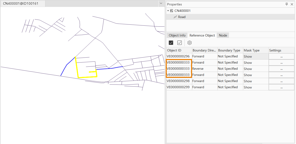
Coordinate positions of feature objects do not match their referenced spatial objects. -
Error Cause
Complex sub-objects in feature objects may create duplicate data segments in internal topology, causing coordinate mismatches.
Handling Steps
-
Check Reference Object
- In the Reference Object of Properties panel, confirm if duplicate edge objects exist.
-
Check Sub-objects
- Switch to Node to verify if the feature object contains multiple sub-objects with duplicated nodes.
-
Editing Correction
- Decompose or split road line objects, or manually edit nodes and adjacent point connection lines in Node to ensure correct internal relationships.
- Re-execute Validate Topology after modifications to confirm error resolution.
Common Error 3: ID = 10017
-
Errors
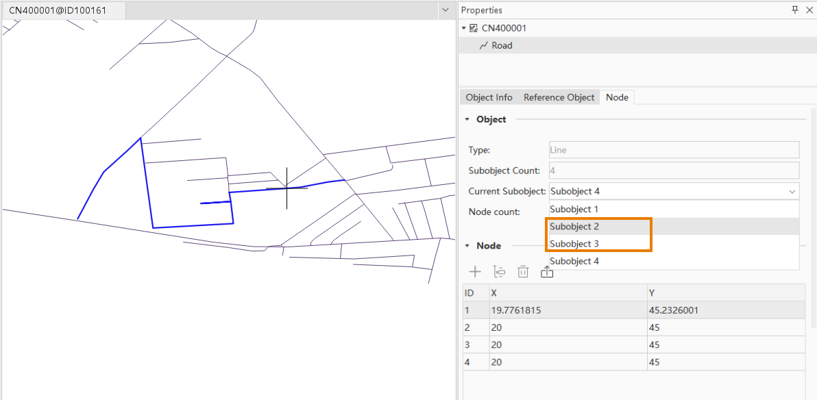
Line feature objects contain multiple sub-objects with discontinuous adjacent nodes. -
Error Cause
When a feature object contains multiple sub-objects, the start/end nodes of adjacent sub-objects may be discontinuous (e.g., sub-objects 2 and 3 in 4 sub-objects are disconnected).
Handling Steps
-
Check Node Continuity
- In the Node of properties panel, confirm node sequence and continuity. As shown in the example road line object, adjacent sub-objects (2nd and 3rd) have disconnected start/end nodes.
-
Editing Correction
- Use splitting, decomposing, or node reconnection functions to ensure smooth transitions between adjacent sub-objects.
- Re-run Validate Topology after editing to confirm resolution.
Common Error 4: ID = 10020
-
Errors
Feature object relationship table cannot find corresponding object based on Feature Object Identifier (FOID). -
Error Cause
Typically caused by outdated relationships after deleting composite or master-slave objects, leading to data reference errors.
Handling Steps
-
Verify Master-slave
- Check Aggregation or Master-slave Relationship Management panel for relationships where the deleted object was a master. As shown in the example, a lateral buoy object referenced in master-slave relationships has been deleted during data updates.
-
Correct Relationships
- If related objects are deleted or inconsistent, rebuild master-slave relationships via Aggregation or Master-slave Relationship Management using updated data.
- For road line objects, use decomposition or adjacent point connection functions to split multi-sub-object lines into independent single-sub-object lines.
-
Validation
- Re-run Validate Topology after saving changes to ensure error elimination.
Related Topics