


Instructions
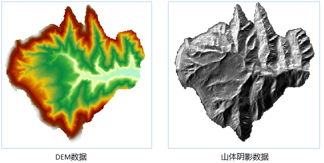
Generate a mountain shadow map using DEM data, and the returned result type is RasterRDD. The shadow map of a mountain is a grid map that reflects the terrain undulation by simulating the original and falling shadows of the actual surface. By using an imaginary light source to illuminate the surface, combined with the slope and aspect information obtained from the raster dataset, the grayscale values of each pixel are obtained. The slope facing the light source has a higher grayscale value, while the slope facing the light source has a lower grayscale value, which is the shadow area, thus vividly representing the actual surface topography and terrain. Due to the highly realistic three-dimensional effect of the mountain shadow map calculated from raster data, it is commonly referred to as a three-dimensional shading map. The three-dimensional shading map has significant value in describing the three-dimensional surface conditions and terrain analysis. When other thematic information is superimposed on the three-dimensional shading map, the application value and intuitive effect of the three-dimensional shading map will be further improved. The 3D shading map is mainly used for display. By overlaying the grid with a 3D shading map and setting the transparency of the grid layer, it is easy to create a beautiful, detailed, and three-dimensional landscape map. In order to achieve the best drawing effect under different Application Scenarios, it is necessary to continuously adjust parameters, such as the transparency and brightness of the grid layer. Afterwards, other layers (such as land use type maps, road and river layers) can be added to it to further enrich map information.
Analysis principle
When generating a 3D shading map, it is necessary to specify the position of the hypothetical light source, which is determined by the azimuth and altitude angles of the light source.
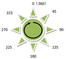
Azimuth is used to determine the direction of a light source and is represented by an angle. As shown in the following figure, starting from 0 degrees due north and measuring clockwise, assign angle values to each direction from 0 degrees to 360 degrees, so the due north direction is also 360 degrees. 90 degrees due east, 180 degrees due south, and 270 degrees due west. The default value for azimuth is 315 degrees.
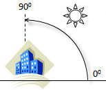
The height angle refers to the inclination angle of the light source when illuminated, ranging from 0 degrees to 90 degrees, as shown in the figure. When the height angle of the light source is 90 degrees, the light source is directed towards the ground. The default value for the height angle is 45 degrees.
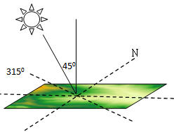
When the azimuth angle of the light source is 315 degrees and the altitude angle is 45 degrees, its relative position to the ground surface is shown in the following figure:
be careful: When conducting mountain shadow analysis, it is required that the unit of the grid value (i.e. elevation) to be calculated be the same as the unit of the x and y coordinates. If there is inconsistency, it can be adjusted through the elevation scaling coefficient (corresponding to the zFactor parameter in the method). However, it should be noted that when the conversion between elevation units and coordinate units cannot be adjusted through fixed values, the data needs to be processed through other means. One of the most common cases is that when the DEM grid uses the geographic coordinate system, the unit is degrees, and the elevation value is meters. At this time, it is recommended to perform projection conversion on the DEM grid and convert x, y coordinates to plane coordinates.
Settings for Zfactor
If the unit of measurement for z (elevation) is the same as x and y (horizontal) units, then the z factor is 1. If the measurement units are different, then a z-factor needs to be defined to explain this difference, as shown in the table below. For example, when using geographic coordinate system data (such as GCS_WGS 84 with longitude and latitude coordinate system), if the elevation is in meters, it is necessary to convert meters to degrees. Then set the conversion factor Zfactor to 0.00001, as shown in the following table.
| From | To | &# 160; | &# 160; |
| &# 160; | Feet | Meters | Degrees |
| Feet | 1 | 0.3048 | 0.000003 |
| 米(Meters) | 3.28084 | 1 | 0.00001 |
Parameter Specification
| Parameter Name | Default Value | Parameter Definition | Parameter Type |
|---|---|---|---|
| RDD to be analyzed | DEM RasterRDD that needs to generate mountain shadows | RasterRDD | |
| Light source azimuth (Optional) |
315.0 | The specified light source azimuth. Used to determine the direction of the light source, it starts from the true north direction line of the light source's location and increases clockwise to the angle between the light source and the target direction line, ranging from 0 to 360 degrees. It is 0 degrees in the true north direction and increases clockwise | Double |
| Light source height angle (Optional) |
45.0 | Light source height angle. The tilt angle used to determine the illumination of a light source is the angle between the direction line of the light source and the target and the horizontal plane, ranging from 0 to 90 degrees. When the height angle of the light source is 90 degrees, the light source is directed towards the ground | Double |
| Elevation scaling factor (Optional) |
1.0 | Elevation scaling factor. This value refers to the unit transformation coefficient of the grid value (Z coordinate, i.e. elevation value) relative to the X and Y coordinates in the DEM grid. Usually, in calculations involving X, Y, and Z, it is necessary to multiply the elevation value by an elevation scaling factor to ensure that the units of the three are consistent. For example, the units in the X and Y directions are meters, while the units in the Z direction are feet. Since 1 foot is equal to 0.3048 meters, a scaling factor of 0.3048 needs to be specified. If set to 1.0, it means no scaling | Double |