In the Marker Symbol Editor, in order to facilitate the creation and editing of point symbols, the Marker Symbol Editor provides tools such as scale, background grid, capture function and other auxiliary symbol editing tools, and users can make necessary settings for these tools. So as to customize the symbol editing environment in line with their own working characteristics, which are collectively referred to as the symbol editor Environment Settings. The following details how to set up the Symbol Editor environment.
Valid Range of the symbol edit area
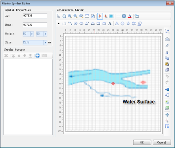
The Valid Range in the symbol editing area is the range marked by the scale. When the drawn object exceeds the Valid Range, the prompt window "Symbol exceeds Visible Bounds:" will pop up. As shown in the figure below, the area filled by the grid is the Valid Range of the symbol editing area, and the content drawn in the Valid Range is the valid content of the point symbol.
 |
Marker Size and Display Size
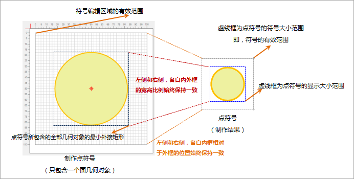
The Valid Range in the symbol editing area corresponds to the Valid Range of the point symbol after creation, as shown in the following figure. In practical application, the display size of the point symbol in the map is determined by setting the Marker Size of the point, wherein the size of the point symbol is divided into Marker Size and Display Size:
- The Display Size of the symbol is the size of the smallest Bounds of all Geometry contained in the pointer symbol.
- Marker Size is the size of the Valid Range of the symbol.
- When you make a point symbol in the symbol edit area, the ratio of the minimum Bounds of the total Geometry drawn (within the Valid Range of the symbol edit area) to the width of the Valid Range of the symbol edit area is equal to the width of the symbol Display Size to the width of the Marker Size. Thus, by setting the value of Marker Size, the value of Display Size of the symbol can be calculated according to the scale, and vice versa.
- When you make a point symbol in the symbol editing area, The Relative between the minimum Bounds of all the Geometry drawn (within the Valid Range of the symbol edit area) and the Valid Range of the symbol edit area determines the minimum Bounds of all the Geometry contained in the point symbol and the symbol's Valid Relative of Range. In this way, the position of the object content of the point symbol relative to the Valid Range of the symbol does not change no matter how the size of the point symbol changes.
The Marker Size of a point symbol is equal to the Display Size if the minimum Bounds range of all Geometry contained in the point symbol coincides with the Valid Range of the point symbol. Usually, the maker of the symbol and the user of the symbol are not the same person, so the user is not clear about the width-height ratio between the minimum Bounds of all Geometry contained in the symbol and the Valid Range of the symbol when the maker of the symbol makes the symbol. The setting of the Display Size of the symbol provides convenience for the user to directly control the display size of the contents of the point symbol.
 |
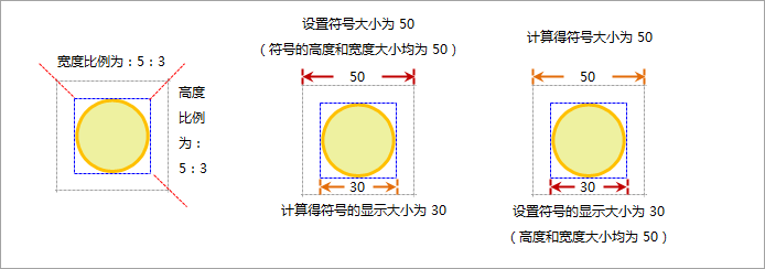
| Marker Size and Display Size Diagram |
If the Marker Size of the point symbol shown in the figure above is set to 50 during Symbol Style Settings, and it is known that the width to height ratio of the Valid Range of the symbol and the minimum Bounds of all Geometry contained in the point symbol is 5:3, then, The Display Size of the symbol can be calculated to be 30; if the Display Size of the symbol is set to 60, the Marker Size can be calculated to be 100.
 |
Symbol Edit Area Background Settings
The background of the symbol editing area is a grid by default. The grid is aligned with the tick marks of the scale. Accurate positioning can be achieved through the grid. In addition, you can use a picture as the background of the symbol editing area, so that the symbol can be drawn in a vectorized way.
- In the Marker Symbol Editor, click the Work Background Settings "button to open the Work Background Settings" dialog box, where you can set the background style of the symbol editing area.
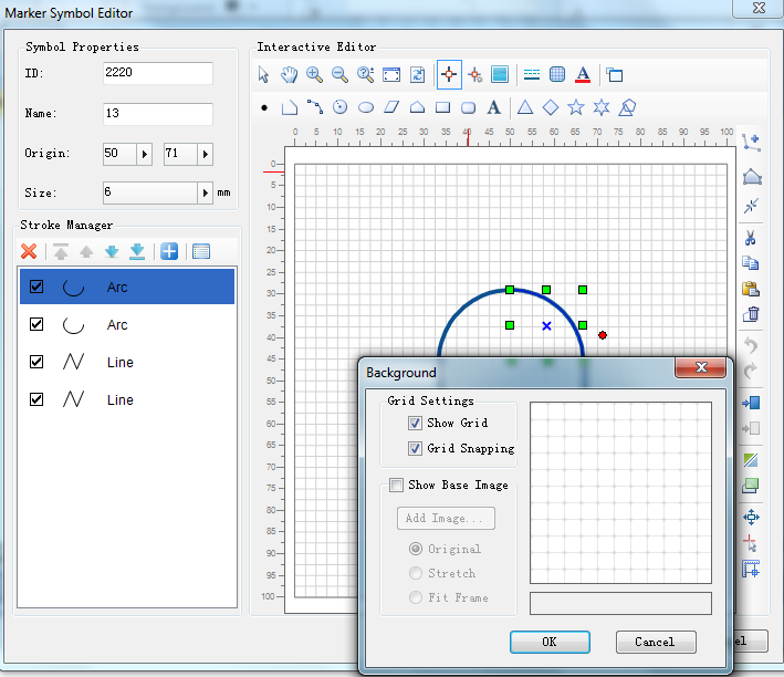
- Whether the background grid in the symbol editing area is displayed can be controlled by checking the "Display Grid" check box: if it is checked, the background grid is displayed; if it is not checked, the background grid is not displayed.
- By checking the "Display grid map" check box, you can add a grid image as the background of the symbol editing area. If the check box is checked, other functions of the area are activated, you can further set the Background Image added to the symbol editing area, and the right side provides a preview function. The effect of Work Background Settings can be seen in real time, specifically:
Add Image: Click the "Add Image" button to pop up the "Open" dialog box. Find the Picture File to be used as the background and open it to add the picture to the symbol editing area as the Background Image.
Original Image: Select "Original Image" to indicate that Picture File Keep Original Size is added to the symbol editing area.
Stretch Map: Select Stretch Map "to indicate that the original picture will be stretched to fill the Valid Range of the entire symbol editing area when added to the symbol editing area.
Adapt to Frame: Select Adapt to Frame "to indicate that the original picture will be stretched so that the width or height of the picture fits the width or height of the Valid Range when it is added to the symbol editing area.
- When the working Environment Settings is finished, click the OK button on the Work Background Settings "dialog to apply the setting results and close the dialog; otherwise, click the Cancel button.
Symbol Edit Area Scale
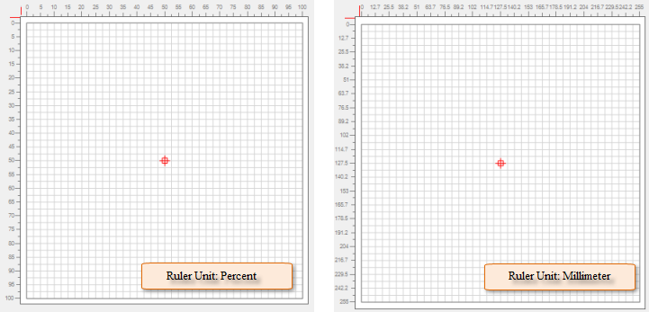
The symbol editing area scale not only identifies the Valid Range of the symbol editing area, but also provides a quantitative standard in the symbol editing process. The numerical unit of the scale is percentage.
 |
Snap Settings
When you edit symbols in a Marker Symbol Editor, you can use snapping to accurately relate strokes and position mouse clicks. There are two types of capture in the symbol editing area, one is to capture the stroke, and the other is to capture the background grid line of the symbol editing area.
- In the Marker Symbol Editor, click the Enable/disable Snap "button to turn snapping on or off in the Symbol Editor area and control whether you want to snap to necessary objects during editing.
- If snapping is turned on in the Symbol Editor area, click the Work Background Settings "button to open the Work Background Settings" dialog box, and check whether the Snap Grid "check box is selected. You can control whether the background gridlines in the Symbol Editor area are captured during snapping: if checked, the gridlines are captured; if unchecked, the gridlines are not captured.
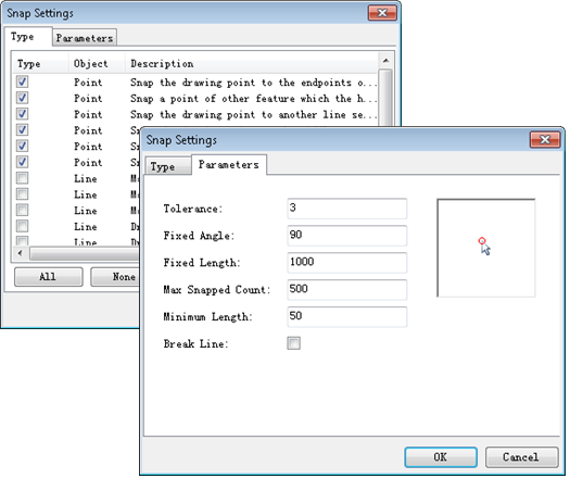
- In the Marker Symbol Editor, click the Snap Settings "button to open the Snap Settings" dialog, which lets you set the snap type and snap parameters.
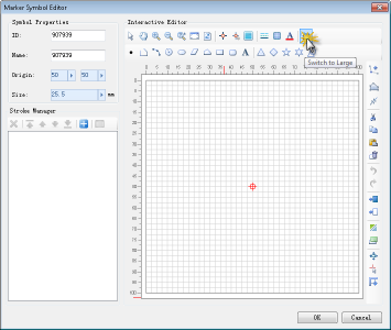
Symbol Editing Area Full Screen
In the Marker Symbol Editor, click the "Switch to Large Icons" "button to make the symbol editing area Full Screen, and press the" ESC "key or the" Switch back to Normal Mode "" button to return to the Normal Mode; You can also click anywhere in the black area of full-screen mode to cancel the full-screen state and return to Normal Mode.