


Instructions for use
Line-of-sight Analysis is a common analysis function in 3D GIS, which is used to judge the intervisibility between any two points in 3D Scene. You can calculate the intervisibility between an observation point and an Observed Point based on the position in 3D space relative to an obstacle provided by a surface or polyhedral feature class. Visibility is determined along the line of sight between these points.
Line-of-sight Analysis requires the user to specify an observation point and an Observed Point, which are in a one-to-many relationship. One observation point can correspond to multiple Observed Points for analysis. An Observed Point can only correspond to one observation point for Line-of-sight Analysis. Analyst Result output lines are divided along the visible and invisible portions of the input line of sight, with green being visible and red being invisible.
Application scenario
Line-of-sight Analysis can be widely used in many aspects, such as judgment of building sight occlusion, monitoring coverage, communication signal coverage, military facilities layout, military firepower coverage and so on.
Operation steps
- Add Model Data to your scene for Line-of-sight Analysis, on the 3D Analysis tab, in the Spatial Analysis group. Click the Line-of-sight Analysis
 button to bring up the 3D Spatial Analysis panel.
 - Click the Add button and move the mouse to the scene. When the mouse status changes to a red dot, you can click the mouse on the data surface to select the observation point.
- After you add a watch point, the mouse state automatically switches to picking an Observed Point. You can continue to add one or more Observed Points. When the DrawObserved Point is moved, the intervisibility between the observation point and the position of the mouse is displayed in real time.
- Meanwhile, select the "Line-of-sight Analysis" "node in the" 3D Spatial Analysis "panel", click the "Add" button in the toolbar, and click to pick and add observation points at appropriate positions in the scene; Select an observation point node in the Line-of-Sight Analysis node directory, and click Add
 in the toolbar to pick the Observed Point corresponding to the observation point at an appropriate position in the scene.
 - When you add an observation point and an Observed Point, the visibility between the observation point and the corresponding Observed Point is analyzed in real time.
- Coordinate information of observation point or Observed Point can be set in the 3D Visibility Analysis panel. Select an observation point or Observed Point in the tree node, and then enter coordinate values in the X, Y and Z text boxes respectively to modify the position of the point.
- The toolbar area provides the operations of adding, importing, exporting, deleting and Export Barrier Point of observation point and Observed Point.
- The resulting Analyst Result is shown in the following figure:
- Stop Info: Select Observed Point under Analyst Result to view the role of the site and Position Info with descriptions of longitude (X), Latitude (Y), and altitude (Z).
- Check HighLight Show Obstacle on the 3D Spatial Analysis panel and the scene will HighLight Show Obstacle. At the same time, the Open attribute table is automatically associated to display the Attributes of the obstacle.
 Button: used to remove the selected Line-of-Sight Analysis observation point or Observed Point in the panel.
  Button: used to import 3D Point Dataset as observation point or Observed Point for analysis.
  Button: The observation point and Observed Point Export as Point dataset recorded by Line-of-sight Analysis can be set, and Dataset saving name and role Select Fields can be set. Select the Line-of-sight Analysis "node
  Button: Select the Line-of- sight Analysis "node in the 3D Spatial Analysis panel, and click the button to pop up the Export Barrier Point" dialog box. Obstacle points in Line-of-sight Analysis results can be exported as 3D Point Dataset.
 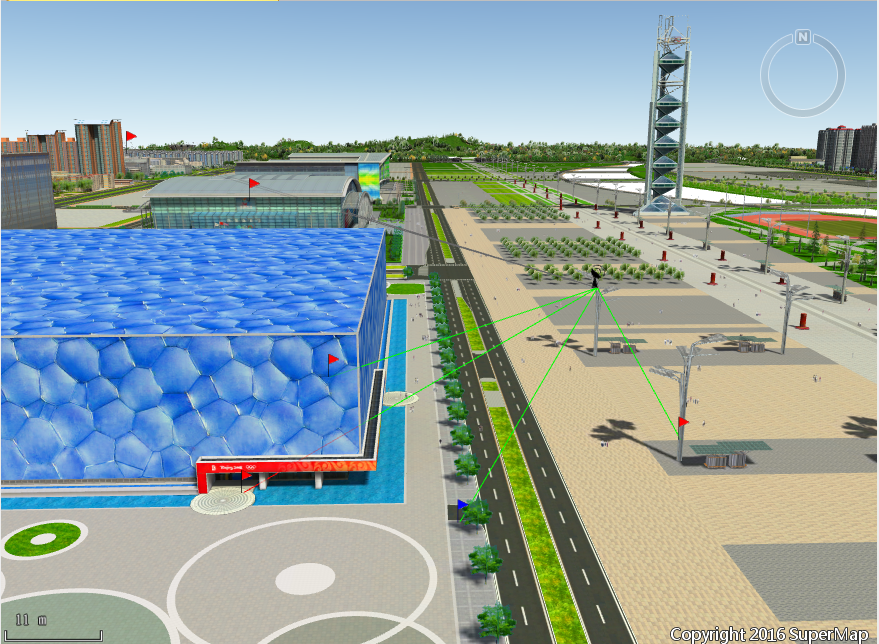 |
| Line-of-sight Analysis Result |
 Precautions
- The maximum angle of multiple lines of sight for 3D Visibility Analysis shall not be greater than 120 degrees, and lines of sight exceeding this value are gray.