


Generate DSM Data
Instructions for use
DSM (Digital Surface Model) refers to the Model Data that contains the elevation information of all the elements on the ground, such as buildings, bridges, trees, etc. The difference between DSM and DEM is that DEM only contains terrain elevation information, but does not contain other surface elevation information. On the basis of DEM, DSM further covers the elevation of other surface features other than ground, and is mostly used in areas where the height of buildings is required.
The Generate DSM function can generate the S3MTile Data (Config File is *.scp) in the specified area of the current scene as DSM data.
Function entrance
- 3D Analysis Tab-> OSGB Group-> Generate DSM
- Toolbox -> 3D Data -> Generate DSM
Operation steps
- New Scene or open the existing scene, load the S3MTile Data of DSM to be generated through the Load 3D Tiles function.
- On the OSGB group of the 3D Analysis tab, click the Generate DSM
 button to bring up the Generate DSM "dialog.
 - Set the scope of action at "Select Range" "in the dialog box. Layer Bounds and Custom Bounds are supported. The specific operations are as follows:
- Layer Bounds: Select the Layer Bounds "radio box to set the union of the All Layers range in the current scene as the Result Data range;
- Custom Bounds: Click and select the Custom Bounds "radio box to set the Result Data range by drawing faces. Click the drawing surface button, move the mouse to the current Scene, click the left mouse button and drag to draw a rectangle as the Result Data range, click the left mouse button after confirmation to complete the setting and return to the dialog box.
- The upper left and lower right at the Result Range "are used to display the range of Result Data.
- In the Result Settings "of the dialog box, you can set parameters such as resolution, camera height, additional height, and the Datasource and name of the Result Dataset. The specific description is as follows:
- Resolution: Used to set the resolution of the generated DSM data. The default is 1 in meters per pixel.
- Camera Height: It is used to set the camera height for generating DSM data. The lower the camera height is, the more detailed the buildings can be seen. The default value is 50 meters, which means that the generated DSM data is the surface conditions seen at the camera height of 50 meters. It is not recommended to be less than maximum height value of the objects in the scene.
- Additional height: Set the additional height of Generate DSM Data. You can enter a positive or negative value as the additional height. The additional height value adjusts the data elevation as a whole.
- Datasource: All the Datasources in the Current Workspace are listed. Select the Datasource where the Result Dataset is stored. Default is the same as Source Datasource.
- Dataset: Used to display and set the name of the resulting DSM Dataset. The default Dataset Name is DatasetDSM.
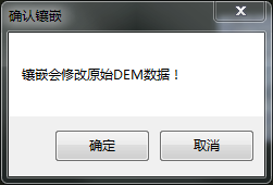
- Mosic To DEM: Check the "Mosic To DEM" "check box, and the prompt" Tessellation will modify the original DEM Data! "" Will pop up. Click the OK button to confirm the check, and click the Cancel button to cancel the check.
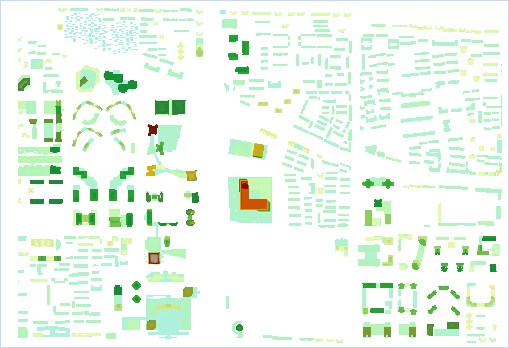
- After setting the above parameters, click OK to execute the operation of generating DSM data. According to the 3D Tiles generated by CBD Scenes in Sample Data, the generated DSM data is shown in the following figure:
 Hint:
Hint: - Result Dataset obtained by
- Generate DSM Data is Raster Dataset. The default coordinate system of DSM Data generated
- based on Spherical Scene is GCS _ WGS 1984 (EPSG Code: 4326), which can be customized and modified.