


Instructions for use
There are a large number of different feature points, inspection wells and ancillary facilities in the 3D pipeline scene. In order to break through the dilemma of manual modeling, which is time-consuming, labor-intensive and difficult to maintain, SuperMap iDesktopX supports the construction of 3D adaptive tube point symbols, 3D Marker and 3D line symbols, which can be saved in the symbol library for repeated use.
3D Marker is used for expression wells and ancillary facilities such as valves and water meters. 3D linetype symbols are used to represent 3D pipelines. Three-dimensional adaptive tube point symbols are used to express turning points, branch points, intersections, transition points, elbows, multi-pass points and other feature points.
New Adaptive Tube Point Symbol
Based on the Topology of pipe points and pipelines in 3D Network Dataset, 3D adaptive pipe point symbols can effectively solve the matching problem between pipe points such as elbows and tees and pipelines in the scene.
- Double-click the "Resources" Marker Symbol Library "in the" Workspace Manager "" or right click and select the "Load Marker Symbol Library" "to open the" Marker Symbol Selector "" dialog box;
- Click the Edit Drop-down Button, and select New 3D Adaptive Symbol.. from the right pull-down menu of New Symbol to open the 3D Adaptive Pipe Symbol Editor "dialog box;
- Parameter Settings
- End Thickness: indicates the length of the hoop of the pipe point symbol. When the parameter value is set to "0", it indicates that the symbol has no hoop;
- Corner Subdivision Number: Indicates the smoothness of the elbow of the tube point symbol. The larger the value, the smoother the elbow effect.
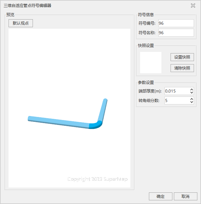
Figure: 3D Adaptive Pipe Symbol Editor. - After modifying the "Symbol Name" and "Set Snapshot", click the "OK" button to complete the creation of the 3D adaptive symbol.
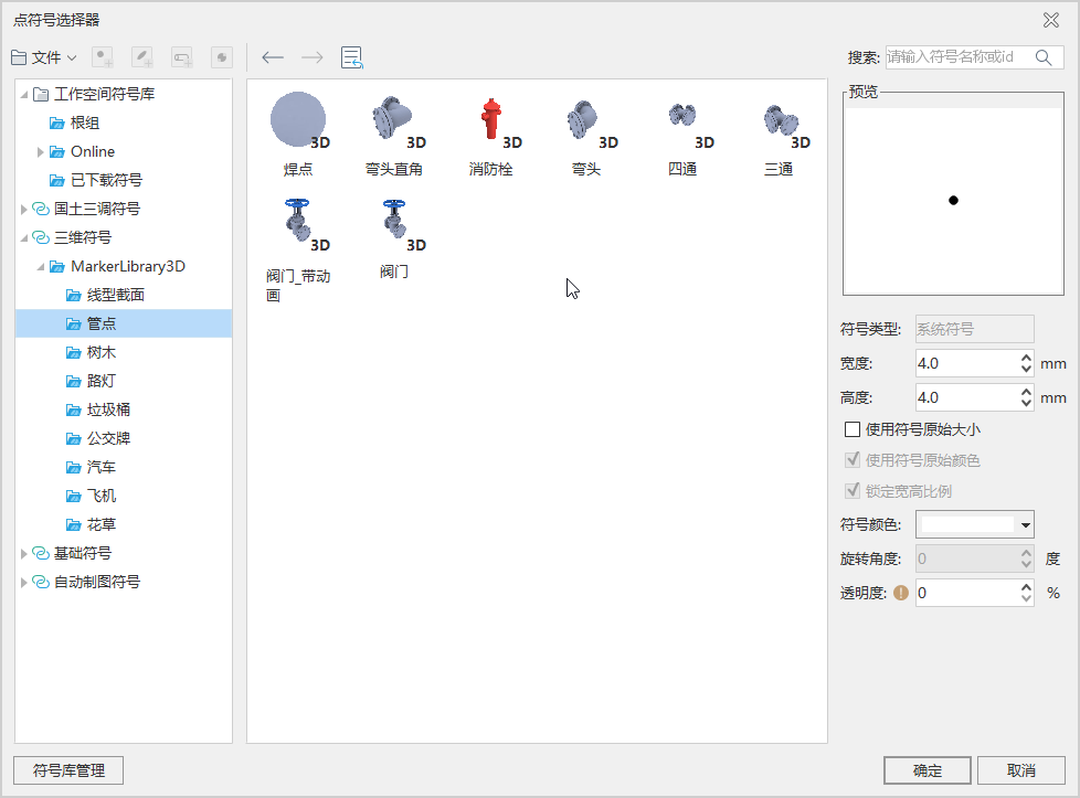 |
| Figure: Marker Symbol Selector. |
New 3D Tube Point Symbol
- Double-click the "Resources" Marker Symbol Library "in the" Workspace Manager "" or right click and select the "Load Marker Symbol Library" "to open the" Marker Symbol Selector "" dialog box;
- Click the Edit Drop-down Button and select New 3D Symbol from the right pull-down menu of New Symbol to open the 3D Marker Editor "dialog box;
- Click the "Set Model" button to pop up the "Open" dialog box, select a self-made Model File (*.sgm or 3ds file), and confirm to open it;
- Set the "Scale Factor" and "Rotation Angle", and the default values can be used;
- After modifying the "Symbol Name", click the "Set Snapshot" button to set the snapshot picture of the symbol, and click "OK" to complete the creation of the 3D Marker.
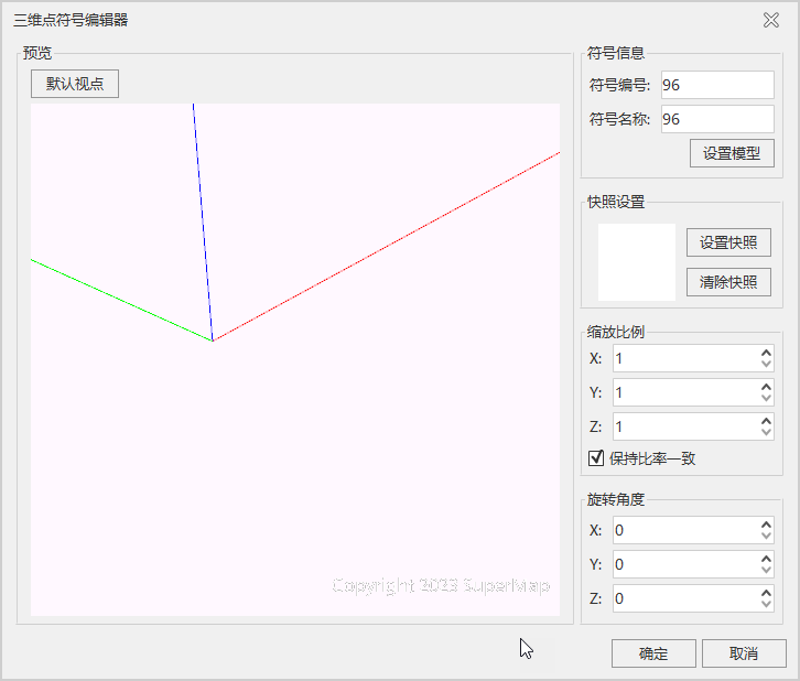 |
| Figure: 3D Marker Editor |
New 3D Pipeline Symbol
- Double-click the "Resources" Line Symbol Library "in the" Workspace Manager "" or right click and select the "Load Line Symbol Library" "to open the" Line Symbol Selector "" dialog box;
- Click the Edit Drop-down Button, and select New 3D Linetype from the right pull-down menu of New Symbol to open the 3D Linear Symbol Editor "dialog box;
- Select a circular section in the "Section List", set the "Line Width" and "Line Color", and then modify the "Symbol Name" and other information;
- Click the "Set Snapshot" button. After setting the Snapshot picture, click the "OK" button to complete the creation of the 3D linetype symbol.
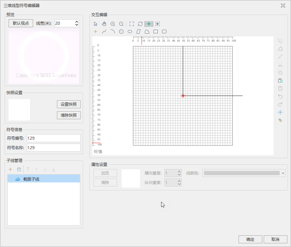 |
| Figure: 3D Linear Symbol Editor |
Batch Build 3D Pipeline Symbol
According to the pipeline section information stored in the 3D Line Dataset, the efficiency of building the 3D pipeline symbol is improved and the manual intervention is reduced.
- Property Field of pipeline section information is required in the property table of 3D Line Dataset to be made into pipeline, and the Type is text type. For example, when the attribute value of the section information is "30", it represents a circular pipe with a diameter of 0.03m; when the attribute value of the section information is "300X100", it represents a square pipe with a length of 0.3m and a width of 0.1m, and the connection symbols between 300 and 100 can be "X", "X", "*".
- In Resource under Workspace, click the Line Symbol Library node, and in the displayed Line Symbol Selector window, Click Build 3D Linear Symbols in Bulk "Drop-down Button and select Batch Build 3D Pipeline Symbol to pop up the Create 3D Linear Symbols in Bulk" dialog box. As shown in the following figure:
- Datasource: Select the Datasource where the 3D Line Dataset to be created is located.
- Dataset: Select the 3D Line Dataset in the Datasource for which you want to create a 3D line type symbol.
- Target Field: Property field that stores pipeline section information.
- After setting the above parameters, click OK to automatically create two Property Fields, SymbolID and LineWidth, in the property table of 3D Line Dataset. The SymbolID attribute value stores the symbolic number of the automatically constructed 3D pipeline, and in the case of a circular pipe route, the LineWidth attribute value stores the diameter of the pipeline section in meters. In the case of square pipe routes, the value of the LineWidth attribute stores the maximum of the length and width of the route section, in meters.
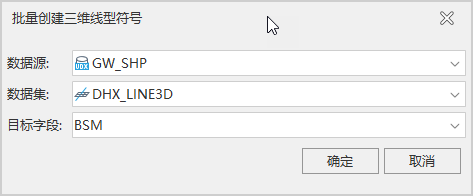 |
| Figure: Create 3D Linear Symbols in Bulk "Dialog |
Precautions
The height mode and data source of the pipeline and pipe point Layer Settings should be consistent, otherwise the pipeline and pipe point will not be displayed correctly due to the inconsistent elevation.
When making a linetype symbol through the 3D Linear Symbol Editor ", if you make a pipeline with a circular section, you can improve the rendering effect and enhance the rendering performance by not checking the Auto Break option.
Although SuperMap GIS supports the linetype symbol section of any shape, it is recommended to use the left-right symmetrical linetype symbol, otherwise the pipeline will not be aligned with the elbow, tee and other pipe points.