


Instructions for use
The valve with complex shape structure can be represented by Model Symbol, but in 3D Scene, the direction of the pipeline changes in X, Y and Z directions, and the valve also needs to adjust the angle "adaptively" according to the direction of the pipeline. If the influence of the model angle is ignored, it will lead to the situation that deviates from the real scene: the pipeline at the bottom of the valve cannot be connected with the pipeline, and the valve switch is covered by the pipeline.
To solve this problem, the following steps can be used to set the adaptive connection between the valve pipe point and the pipeline:
- Create a new 3D Marker and click "Set Model" to select the self-made Model File (*.sgm or 3ds file) as the valve model.
Note: When making the valve model, the pipeline at the bottom of the valve should be along the X axis, and the valve opening and closing should be along the Z axis. If the direction of the Model Symbol is not consistent with this setting, set the Rotation angle so that the bottom pipe is along the X axis and the switch is along the Z axis.
- Make a Custom Thematic Map for the tube point layer, and designate a Property Field as the Marker Style of the thematic map;
- Sets the Pipe Layer Parameter Settings of the Pipe Points thematic layer to Model Match Pipeline Mode.
- After setting, the valve model will adjust the angle adaptively according to the pipeline direction, that is, the bottom pipeline of the valve is along the pipeline direction, while the opening and closing of the valve is perpendicular to the pipeline direction. The effect is shown in the following figure:
 |
| Figure: New 3D Marker (Bottom pipe along X axis, switch along Z axis) |
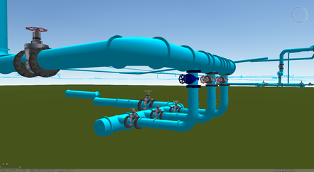 |
| Figure: After setting the adaptive valve, the valve model is connected with the pipeline correctly. |