


Common infrastructure in our real world, such as municipal water networks, power lines, natural gas pipelines, telecommunications networks, and water systems. The essence of these networks is the network structure of directional flow of resources, which can be modeled and analyzed through the facility network.
Facility Network Analysis is one of the Network Analysis functions, which is mainly used for various connectivity analysis and tracking analysis.
Facility Network Analysis needs to build a network model according to certain rules, and the facility network must have a flow direction. This is what makes Facility Network Analysis special. The so-called flow direction is the direction of material flow. The flow direction in the network depends on the topology in the network, the network position of the source and the sink.
Basic concepts
The essence of a facility network is the combination of a set of edges and junctions, and the real world network facilities are represented and modeled by certain connectivity rules. That is, the user specifies how the resource to be modeled flows in the setup network by specifying the meaning and rules of the basic elements (dot-line objects) that constitute the facility network.
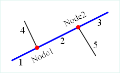 |
| Figure 1: Schematic diagram of the facility network |
Figure 1 shows a schematic diagram of a simple facility network. The thick blue line is the main pipeline, which is composed of three sections 1, 2 and 3. The thin black lines 4 and 5 are the branch pipelines. The red junction points Node1 and Node2 are the junction points of the main pipeline and the branch pipeline.
- Edges: The constructed facility network generally contains line objects, which are used to represent the resource flow pipeline in the facility network model. For example, water pipes, electric wires, natural gas pipelines and so on can be regarded as the edge of the facility network.
- Simple Edges: Simple edges refer to the edges that can only connect two junction points at both ends, such as the branch water pipes (4 and 5) shown in Figure 1, one end of which is connected to the main pipeline and the other end is connected to other secondary pipelines. In other words, a simple edge does not have internal connectivity, and if a new intersection point needs to be added, it must be physically broken into two simple edges.
- Complex Edges: Complex edges can have junction points added to them in addition to the junction points at the beginning and end of simple edges. As shown in the blue water network main pipeline in fig. 1, although it connects two branch pipelines through junction nodes Node 1 and Node 2, it is not really broken, that is, it can add any number of junction points in the middle without being really physically broken.
- Junctions: The constructed facility network generally contains point objects, which are used to represent the junction location of two or more resource circulation pipelines in the facility network model, such as the pump station and valve of the water network, the electric gate of the power grid, the gas supply point of the natural gas network, etc.
- Source: It refers to the intersection point of resource outflow, such as power station and water station in the real network.
- Sink: It refers to the intersection point of resource inflow, such as the access point of power grid and water network users in the real network.
- Network weight: Each network can be associated with a set of weights. For example, in a water network, there can be a water pressure weight, which is associated with the length of each edge. The expression means that the water pressure will continue to decrease due to the existence of pipeline friction every time the water flows through a pipeline. A network weight can be associated with a certain field of a certain class of objects, and can also be associated with a variety of objects, and the weight can be 0, for example, the weight of an isolated intersection point that is not associated with any field is 0.
- Valid and invalid elements: The edges and junctions in the facility network can fail for some reason (for example, a valve is closed, causing a section of water pipe to be unable to flow). The invalid edges or junctions become obstacles to the network. Valid and invalid elements can be represented by a field.
Note: There is no concept of complex edges in the existing system of universal GIS kernel, that is, all complex edges are physically interrupted when they appear and are treated as simple edges.
The values in the Flow Direction Field represent special meanings and are described as follows:
| Numerical value | Meaning |
| 0 | Indicates that an arc segment flows in the network from a starting point (FromNode) to an ending point (ToNode). |
| 1 | Indicates that an arc segment flows in the network from an end point (ToNode) to a start point (FromNode). |
| 2 | Indicates uncertain flow direction, including loop and uncertain flow direction. |
| 3 | Indicates that the arc segment is not connected. |
As shown in the figure below, it is the display effect after establishing the flow direction of a river network. Different colors and linearity represent different flow directions. The meanings of the numbers in the legend are described in the table above.
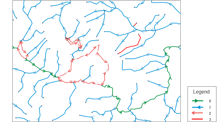 |
| Figure: Flow direction setting effect |