


The Calibrate Route helps ensure that the measurements are correct and that the event is accurately located. Calibrating the scale values of Route Data with reliable reference point data is an important step in Dynamic Segmentation. For example, the Route Data of a highway, whose scale value is the mileage information of the highway, may not be accurate enough. After re-collection by surveyors, a point is collected every 200 meters along the highway, and the corresponding mileage is measured and recorded by instruments. The newly collected data can be used as reference point data to correct the existing Highway Route Data to ensure the accuracy of the subsequent Dynamic Segmentation results.
Procedure for Calibrate Route
Calibrate Route is the process of adjusting the scale value of the route by reading the scale value of the reference point. The Calibrate Route process is described as follows:
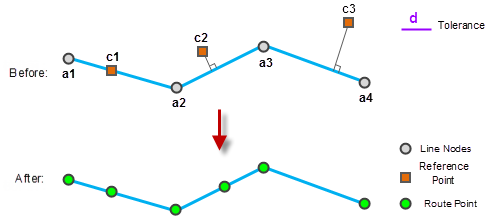 |
| Figure: Diagram of Calibrate Route |
- The reference point and the route are in one-to-one correspondence through the route identification field. The reference point data and the Route Data respectively have a route identification field, and the reference point with the same ID as the Route Data identification field is regarded as the reference point corresponding to the route.
- When the corresponding reference point falls on the route and coincides with a node, the M value of the node uses the M value of the reference point.
- The M values of the nodes on the route that do not overlap the corresponding reference points are interpolated using the M values of the reference points that lie within the calibration tolerance.
- Reference points that lie outside the calibration tolerance will not participate in the calibration.
Calibration mode
Application provides two calibration methods: Calibrate by Distance and calibration by scale.
 |
 |
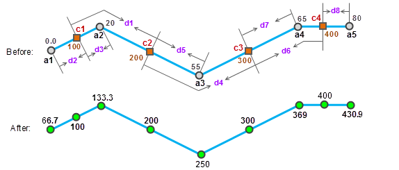
| Figure: Calibrate by Distance diagram | |
The Calibrate by Distance comprises the following steps:
And calibrate by using that scale value on the route position correspond to the reference point. This calibration maintains the regularity of the original Route Data scale values (such as increment, decrement, or jump). This approach is very useful for fine tuning the scale value of a route when the ratio of the length of the route being calibrated to the scale value is different.
 |
 |
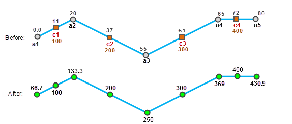
| Figure: Schematic diagram of calibration by scale | |
Calibrate by scale as follows:
- Calibrate by Distance The M value is calculated
based on the distance between the two points along the route. A monotonic calibration result can be obtained by means of Calibrate by Distance, that is, the value of M after calibration is increased or decreased.
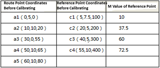
- For node A1, C1 and C2 are used for calibration. First, the distance D1 between C1 and C2 is calculated, and then the calibration rate R1 = D1/ (200-100) is calculated. Note that the distance mentioned here refers to the distance along the line.
- Then the distance D2 between A1 and C1 is calculated, so that D2/ (100-Ma1 ) = R1, and the calibrated M value of A1 is 100-d2/R1.
- Similarly, use C1 and C2 to calibrate A2. First calculate the distance D3 between C1 and A2, and then calculate the calibration rate R2 = D1/ (200-100), then D3/ (Ma2-100 ) = R1, then the calibrated M value of A2 is: 100 + D3/R1. And so
- on, using C2 and C3 to calibrate a3, and using C3 and C4 to calibrate A4 and a5. Note that the calibration rate is always calculated by sampling the two reference points closest to the point being calibrated. The M value of each node of the route after
- calibration is shown in the figure after calibration above.
- Calibrate to Scale
- Node A1 is calibrated
- using reference points C1 and C2. First, calculate the calibration rate of M value R1 = (37.5-10)/ (200-100), where (37.5-10) is called the line scale difference of the points of C1 and C2 on the original line. The exact line scale difference between
- A1 and C1 is (10-0), so (10-0)/ (100-Ma1 ) = R1, and the calibrated M value at A1 is 100- (10-0)/R1.
- Similarly, use C1 and C2 to calibrate A2. First, calculate the calibration rate R2 = (37.5-10)/ (200-100), and the accurate line standard difference between A2 and C1 is (20-10), then (20-10)/ (Ma2-100 ) = R2. The calibrated value of M at point A2 is 100 + (20-10)/R2.
- And so on, calibrate the remaining nodes in turn: calibrate A2 using C1 and C2, calibrate a3 using C2 and C3, calibrate A4 and a5 using C3 and C4. The M value of each node of the route after
- calibration is shown in the figure after calibration above.
 Caution:
 of Calibrate Route require at least two reference points for Calibrate Route, and the two reference points nearest to the node to be calibrated are used for calibration.