


In the process of collecting and editing Spatial Data, some errors will inevitably occur. For example, the same node or the same line is digitized twice, and the adjacent surface objects are cracked or intersected or not closed in the acquisition process. These errors often lead to Topology errors such as false nodes, redundant nodes, suspended lines and repeated lines. As a result, the Topology of the collected Spatial Data does not match the Topology of the actual ground objects, which will affect the subsequent Data Processing and analysis work, as well as the quality and availability of the data. In addition, these Topology errors are usually large and hidden, which are not easy to be identified and removed by manual methods. Therefore, Topology Processing is needed to fix these redundancies and errors.
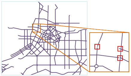 |
| Figure: Topology error diagram |
Topology Processing is the process of Repair topology error or avoiding Topology error, including two steps of inspection and repair. Topology Processing includes Remove Pseudo Nodes, Redundant Vertices, Remove Duplicate Lines, Remove Overshoots, Extend Undershoots, In order to achieve the best processing effect, it is necessary to set the corresponding tolerance for different rules in Topology Processing, such as Merge Adjacent Ends and Intersect Arcs.
In this product, Topology Processing is mainly performed for Line Dataset, and Region Dataset or Network Dataset can be constructed for the processed Line Dataset. You can also use the Validate Topology function to perform a more detailed Topology Check operation. The operation functions involved in Topology Processing include Line Dataset Topology Processing, Topology Surface Construction and Build Topology Network.
The use of each Topology Processing rule is described in turn below.
- Remove Pseudo Nodes
A pseudonode is a point that connects two arcs.
When the false node has no practical significance, the operation of the Remove Pseudo Nodes can be executed to remove the false node and merge the two arc segments connected with the false node into one.
As shown in fig. 1below, Points A and B are false nodes without practical significance and need to be removed. The processing results are shown in Figure 2 below.
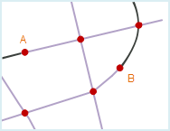
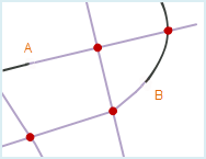
Figure 1 Figure 2 - Redundant Vertices When there are multiple nodes with the same meaning and close distance on
a line object due to operational problems, only one node is correct, and the other nodes are redundant nodes, referred to as redundant points.
When a line object has two or more nodes whose distance is Less than or equal to the specified Fuzzy, only one node remains after Topology Processing, and the other points are removed as redundant points. Fuzzy can be set in the properties window of the Dataset where the line object is located.
As shown in Figure 1 below, on line object A, the distance between point A and point B is less than Fuzzy value, so point A will be removed as a redundant point during Topology Processing, and only point B will be retained. The processing result is shown in Figure 2 below.
Similarly, on the line object a, the distance between the point C and the point D is also less than Fuzzy value, and the point C will be removed as a redundant point during Topology Processing. The processing result is shown in Figure 2 below. Line object B is not affected by Topology Processing because the end point (i.e., node) C 'of line object B coincides with node C of line object a, and the two line objects do not share the same intersection point. If you want to remove point C and merge point C 'with point D in Topology Processing, you need to select both Redundant Vertices and Intersect Arcs.
Similarities and differences between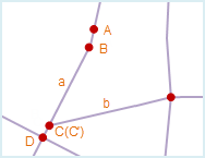
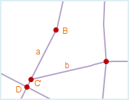
Figure 1 Figure 2 false nodes and redundant nodes:
- Both Redundant Vertices and Remove Pseudo Nodes remove superfluous points.
- Redundant nodes must be redundant and must be removed, while false nodes need to be retained when they are meaningful.
- Redundant point is generally caused by mouse clicking during Draw Line Objects in the process of vectorization, and the point is connected to a continuous and complete line object; while the false node is generally generated when merging or capturing the drawing line near the end point, and the point is connected to two line objects.
- Redundant points are nodes, that is, points on the line object other than first and last endpoints; false nodes are nodes, that is, the endpoints of the line object.
- Remove Duplicate Lines
Without considering the direction of the line object, when the All Nodes in two line objects coincide in turn (that is, the coordinates are the same) or the distance between the nodes is less than Fuzzy, the two line objects are said to coincide, and one of the line objects is called a duplicate line. Fuzzy can be set in the properties window of the Dataset where the line object is located.
To avoid generating polygon face objects with zero or very small area when building a topological polygon, only one of the two coincident line objects will be retained after Topology Processing, and the duplicate line will be deleted.
As shown in fig. 1 below, the line object AB is coincident with the line object A 'B', where the 'B' is a repeating line. In order to better distinguish the repeated lines, the 'B' are represented by other colors here. After Topology Processing, the duplicate line A 'B' is removed, resulting in Figure 2 below.
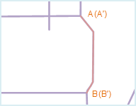
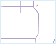
Figure 1 Figure 2 - Remove Overshoots
If the endpoint of an arc segment is not connected with the endpoint of any other arc segment, the endpoint is called a suspension point, and the arc segment containing the suspension point is called a suspension line. Where a short hanging line is a line object with a short hanging portion.
Afterchecking Remove Over shoots, you need to set the tolerance range that makes this rule valid. When the length of the hanging part is less than set tolerance range, the hanging part will be deleted after Topology Processing. Bounds Settings for Remove Over shoots tolerance must be less than 100 times Dangle. If tolerance is set to 0, default tolerance will be followed. Dangle can be set in the properties window of the Dataset where the line object is located.
As shown in Figure 1below, line objects a, B, and C contain suspension lines respectively, where a and B are short suspension lines, and the length of the suspension part is less than set tolerance, which will be removed after Topology Processing; If the length of the hanging part of C is greater than set tolerance, it will be retained after Topology Processing. The results are shown in Figure 2 below.
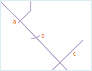
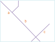
Figure 1 Figure 2 - Extend Undershoots
If the endpoint of an arc segment is not connected with the endpoint of any other arc segment, the endpoint is called a suspension point, and the arc segment containing the suspension point is called a suspension line. Where a long hanging line is a line object with a longer hanging portion.
Afterselecting Extend Under shoots, you need to set the tolerance range for this rule to be valid. When the distance from the endpoint of the long suspension line to the nearest line object is less than set tolerance range, the long suspension line will extend to intersect with the nearest line object after Topology Processing. Bounds Settings of Extend Under shoots tolerance must be less than 100 times of Dangle. If tolerance is set to 0, it will be treated as default tolerance. Dangle can be set in the properties window of the Dataset where the line object is located.
As shown in Figure 1 below, line objects a, B, and C have long suspension lines respectively, where the distance between the long suspension lines a and B and the nearest line object d is less than set tolerance, and the two suspension lines are extended to the line object d after Topology Processing; The length of the suspension line C extending to the nearest line object d is greater than set tolerance, and will be retained after Topology Processing. The results are shown in Figure 2 below.
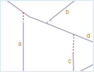
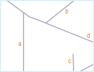
Figure 1 Figure 2 - Merge Adjacent Ends
When the distance between the endpoints of multiple arc segments is less than Fuzzy, these endpoints are called adjacent endpoints. After Topology Processing, these adjacent endpoints are merged into one endpoint. Fuzzy can be set in the properties window of the Dataset where the line object is located.
It should be noted that if the distance between only two endpoints is less than Fuzzy, a false node will be generated after merging.
As shown in Figure 1below, there are adjacent endpoints at A and B, which will be merged into one node after Topology Processing. A false node will be obtained after merging at a, and the "Remove Pseudo Nodes" "operation needs to be performed again.
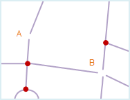
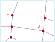
Figure 1 Figure 2 - Intersect Arcs
When one or more line objects are in an intersection relationship, the Intersect Arcs operation can break the line object from the intersection point and decompose it into a plurality of simple line objects in a connected relationship.
TheIntersect Arcs operation can effectively avoid the omission of face objects or the generation of face objects that overlap each other when creating topological polygons.
As shown in Figure 1 below, line objects a and B intersect and respectively intersect with line object C. After Topology Processing, these three line objects will be broken from the intersection, resulting in multiple line objects and three nodes: point A, point B, and point C. The results are shown in Figure 2 below.
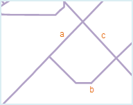
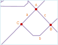
Figure 1 Figure 2 In practical applications, the situation will be more complex, some intersecting line objects need to retain their intersection relationship, and can not be decomposed at the intersection point. At this time, you can set a field to record whether the line is broken in the property table of the Dataset where the line object is located, and control whether the line object is broken by entering Filter Expression.
- Non-broken object: After the Filter Expression is set, the system will not break the line object that meets the expression. Click the button on the right
 to pop up the SQL Expression dialog box, where the user can enter the expression. See the SQL Statement Query for details.
 - Non-break position: Determine the non-break position by selecting the Point Dataset listed in the drop-down list on the right. Determine whether the line object will be broken by judging whether the distance between the point object in the selected Point Dataset and its adjacent line object is within the tolerance range.
If the non-breaking object is not set, the Intersect Arcs operation is performed on all line objects by default; if the non-breaking position is not set, the Intersect Arcs operation is performed on all line objects by default; if the non-breaking line object and the non-breaking position are set at the same time, the system will process the union of the two objects.
- Non-broken object: After the Filter Expression is set, the system will not break the line object that meets the expression. Click the button on the right
 Caution:
 - Different combinations of Topology Processing options
- can be selected according to the actual data and the purpose of use.
- It is recommended to check Intersect Arcs before Topology Processing to get better Topology Processing results. Topology error will be modified on the Source Dataset during Topology
- Processing. If you want to keep the data in the Source Dataset, The Source Dataset needs to be backed up before Topology Processing.
- Intersect Arcs operation results in a true node, while Merge Adjacent Ends operation sometimes results in a false node. Therefore, the operation of the Remove Pseudo Nodes may need to be continued after the operation of the Merge Adjacent Ends. The results
- of Topology Processing are related to the setting of the topology tolerance size. The recommended tolerance is the default value.