


1 Display Effect Settings
1.1 Optimize Fonts Display Effects
<IsSupportClearType></IsSupportClearType> This parameter is used to control whether to enable ClearType support. It can be used to optimize the screen Display Effects and make the font display smoother. There are two cases for this parameter value:
1. true indicates that ClearType support is enabled .
2. false means that ClearType support is not enabled . This value is the default.
Note:
The Microsoft YaHei font with the same font size as the previous component version, The sizes in SFC , UGC , ESRI and WORD are different. In the SuperMap Objects. NET. 6 R (2012) Service Pack 3 optimizes the Display Effects of Microsoft YaHei fonts, with the same font size as Word . However, the effect should be specified in the parameter < IsSupportCle arType > Works when is true . Compared with the SuperMap Objects. NET 6R (2012) Service Pack 2 , the characters with the same font size will become larger in the new version. Please pay attention to it when using it.
1.2 Map display and plotting resolution
The Parameter Settings of map display and plotting resolution are realized by the following three parameters:
l <CustomDPIEnable></CustomDPIEnable> Controls whether to enable the use of User Custom DPI , that is, whether the settings of the following two DPI parameter values take effect. There are two values for this parameter: true for on and false for off. The default value is true .
l <CustomDPIX></CustomDPIX> The value of the custom DPI in the horizontal direction. The default is 96 .
l <CustomDPIY></CustomDPIY> The value of the DPI in the vertical direction for the customization. The default value is 96 .
The CustomDPIX and CustomDPIY Config File parameters are used together. The parameter is the original. Results of CustomMapRatioX and CustomMapRatioY parameter changes, If the user wants to achieve the default Display Effects of map display and plotting before the change through the new parameters of CustomDPIX and CustomDPIY, Both parameter values need to be modified to 76.2 .
1.3 Optimize the scene Display Effects
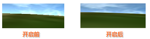
The following two parameters optimize the scene's screen Display Effects through full-screen anti-aliasing settings.
l <IsSceneAntialias </IsSceneAntialias> Controls whether the full-screen anti-aliasing function is enabled. There are two values for this parameter: true for on and false for off.
Turning on the full-screen anti-aliasing function will optimize the fineness of the scene and reduce the appearance of jagged edges of the model in the scene.
Enabling the full-screen anti-aliasing function will increase the occupation of system resources. Please set it reasonably according to the hardware configuration of the user's computer and the full-screen anti-aliasing coefficient ( SceneAntialiasValue ).
l <SceneAntialiasValue></SceneAntialiasValue> Sets the full-screen anti-aliasing factor. The parameter value is an integer between 0 and 16 . The default value is 2 . The full-screen anti-aliasing coefficient represents the intensity of anti-aliasing processing. The higher the value is, the smaller the scene sawtooth is, the more delicate the scene is, and the higher the system resource occupancy rate is. Too high full-screen anti-aliasing coefficient may cause the decline of scene performance. Please set it reasonably according to the actual situation.
1.4 Drawing of map symbols
<SymbolDrawWithLineBrushColor></SymbolDrawWithLineBrushColor> This parameter affects the drawing of point symbols in the map. If the face strokes in the point symbol are not pinned to the Border Color and Fill Color, If the SymbolDrawWithLine BrushColor value is true , when the face stroke of the point symbol is drawn in the map, The linecolor and fillforecolor from the GeoStyle of the current point object are used The drawing of the face stroke border and the fill is performed respectively according to the color value of; if If the value of SymbolDrawWithLine BrushColor is false , when drawing the face stroke of the point symbol in the map, The face stroke border and fill are drawn using the linecolor color values from the GeoStyle of the current point object , that is, the border of the face stroke is the same as the Fill Color.
1.5 Custom Display Engine
The following two items are related to customizing the display engine:
l <CustomGraphicsEnable></CustomGraphicsEnable> Set whether to use the display engine type of User Custom. This parameter has two cases: true indicates to use the display engine type of User Custom, that is, the type specified by the following parameter; false means that the display engine type of the User Custom is not used, that is, the content specified by the GraphicsType parameter is invalid.
l <GraphicsType></GraphicsType> Sets the display engine used. There are two types of this parameter: 1 indicates the Windows display engine; 9 indicates a cross-platform memory display engine.
1.6 High precision display optimization
< IsHighPrecisionMode> </IsHighPrecisionMode> Set whether to enable the High-precision Display Mode. The value of this parameter has two cases: true means enabled; false means not enabled.
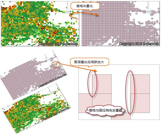
High-precision Display Mode can make the coordinate position more accurate. In practical application, there may be such a situation that Raster Layer and Vector Layer are displayed in superposition, but there is a slight deviation in the position of the same object in the two layers. By turning on the high-precision Display Mode, the slight deviation can be eliminated, so that the coordinate position is more accurate and the precision is higher.
As shown in the figure below, it is the effect of not turning on the high-precision Display Mode. After vectorizing a certain Raster Data, superimpose the generated face Vector Data and the original Raster Data. Theoretically, the two should be completely overlapped. However, when the image is magnified to a certain multiple, it can be seen that the grid in some areas is not completely consistent with the corresponding face object. If the high-precision Display Mode is turned on, this situation can be avoided and the accuracy can be greatly improved.
1.7 Whether to turn on image sharpness enhancement
<IsImageClearer></IsImageClearer> Set whether to turn on the enhanced image sharpness in the scene. Setting this option to true will affect the Visible Bounds of the image:. There are two types of this parameter: true means that the enhanced image sharpness is turned on, but Visible Bounds: will be smaller; false means off (off by default), but Visible Bounds: will be larger.