Build Pipeline Model
 Introduction
The function of Build Pipeline Model is used to set the fields for the node symbols, pipeline symbols, and node and pipeline symbol scaling, in order to match your 3D network dataset with the proper node and line symbols.
Basic Steps
- In the window of Environment Settings, click the button of Pipeline Model Settings button, and select Build Pipeline Model item from the dropdown list. The following dialog box will pop up:
- In the section of Network Parameters, select a 3D network dataset and its datasource.
- Set the fields required to build the pipeline model, including Node ID, Valve ID, Start Node ID and End Node ID.
- In the section of Model Symbols, set the fields that identify the joints and pipelines respectively in the network. The field for joints has all the index numbers for different types of joints, and The field for pipelines has all the index numbers for different types of pipelines.
- In the section of Joint Model Rotate, select the fields that have the x, y, z rotation angles for all the joint symbols and pipeline symbols, as well as the scale factors.
- Click OK to complete. Then all the fields are specifed, and the underground pipeline network can be built.
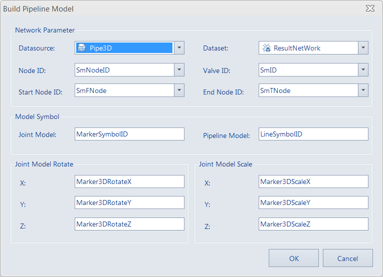 |
| Figure: Build Pipeline Model |